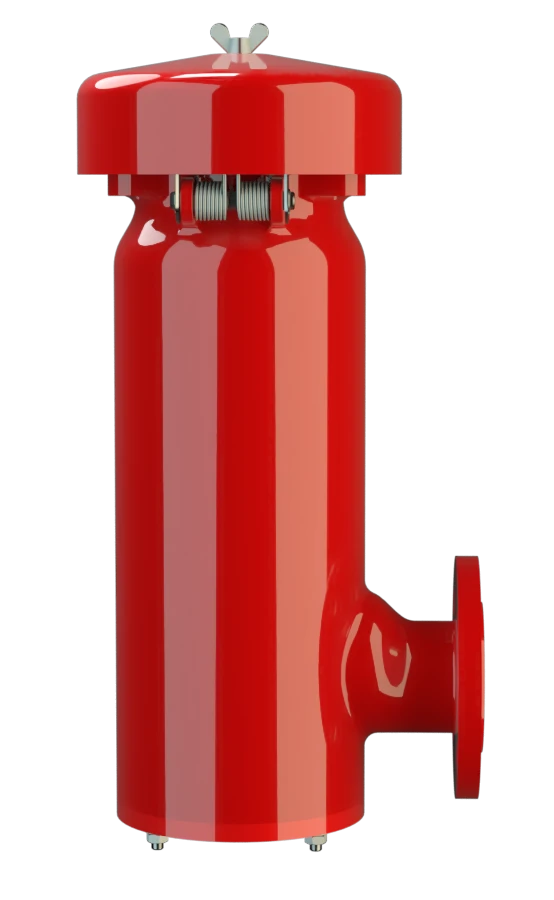
PV/EB
Pressure/Vacuum Relief Valve deflagration- and endurance burning-proof
Features
10% Technology
Extreme Tightness
Optimum Pressure Maintenance
More Efficient Opening and Closing
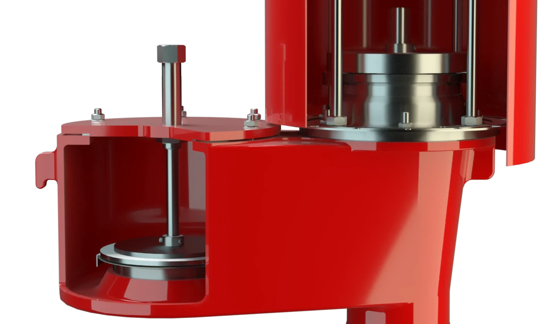
Guided Valve Pallet
Protective System According to ATEX
Use as Detonation-Proof Check Valve
Lifting Device
Modular Design
Intergrated Flame Arrester
Combined Pressure and Vacuum Relief Valve
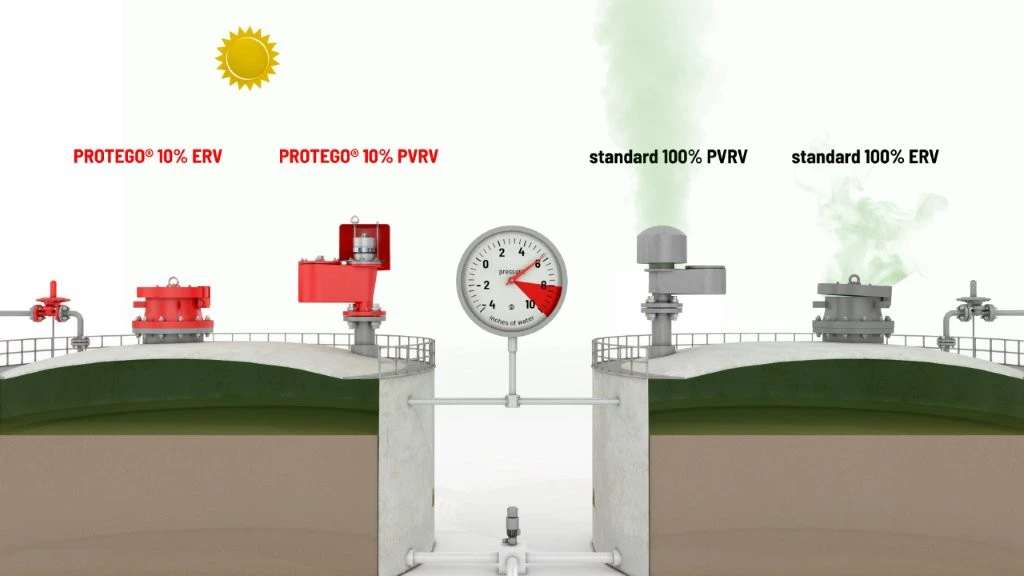
10%-Technology
Advanced Manufacturing Technology
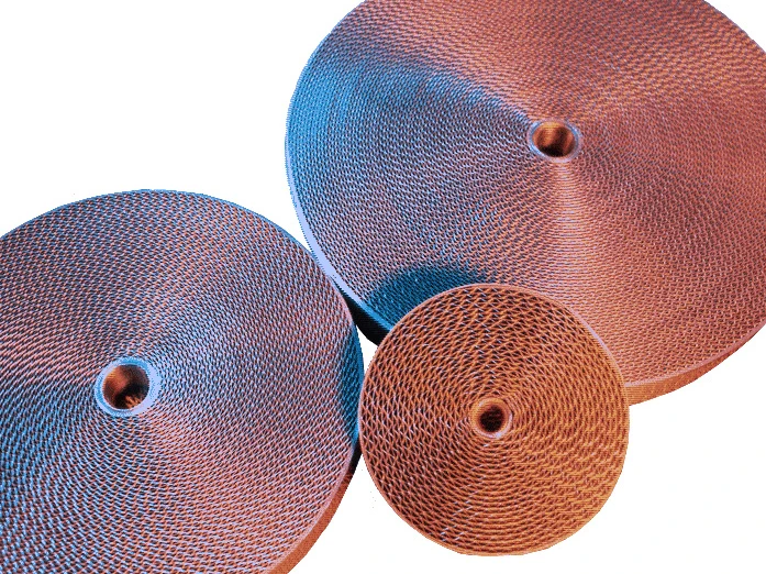
Main Component – PROTEGO® Flame Arrester Unit

Many Individual Certifications
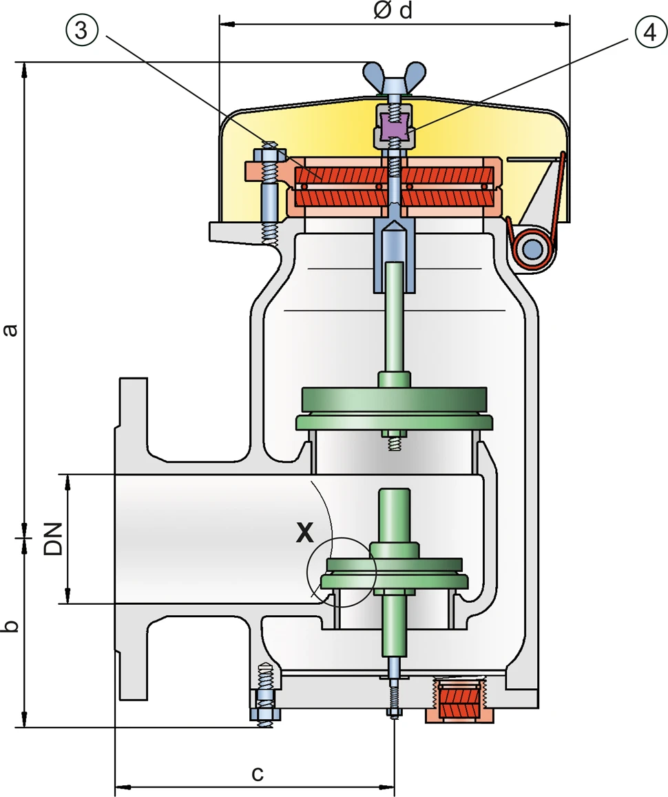
Dimensions
To select the nominal size (DN), please use the flow capacity chart on the following page
| DN | 50 / 2" | 50 / 2" | 80 / 3" | 80 / 3" | |
| Set pressure | ≤ +60 mbar | > +60 mbar | ≤ +60 mbar | > +60 mbar | |
| Set pressure | ≤ +24.1 inch W.C. | > +24.1 inch W.C. | ≤ +24.1 inch W.C. | > +24.1 inch W.C. | |
| a | 308 / 12.13 | 443 / 17.44 | 308 / 12.13 | 443 / 17.44 | |
| b | 108 / 4.25 | 108 / 4.25 | 108 / 4.25 | 108 / 4.25 | |
| c | 165 / 6.50 | 165 / 6.50 | 167 / 6.57 | 167 / 6.57 | |
| d | 218 / 8.58 | 218 / 8.58 | 218 / 8.58 | 218 / 8.58 |
Dimensions in mm / inches
Dimensions for pressure/ vacuum relief valve with heating jacket upon request
Selection of explosion group
| MESG | Expl. Gr. (IEC / CEN) | Gas Group (NEC) |
| > 0,90 mm | IIA | D |
Special approvals upon request
Material selection for housing
| Design | B | C |
| Housing | Steel | Stainless Steel |
| Heating jacket(PV / EB-H-...) | Steel | Stainless Steel |
| Valve seat | Stainless Steel | Stainless Steel |
| Weather hood | Steel | Stainless Steel |
Special materials upon request
Material combinations of flame arrester unit
| Design | A |
| FLAMEFILTER® cage | Stainless Steel |
| FLAMEFILTER® | Stainless Steel |
| Spacer | Stainless Steel |
Special materials upon request
Material selection for pressure valve pallet
| Design | A | B | C | D |
| Pressure range [mbar] [inch W.C.] | +2.0 up to +3.5 +0.8 up to +1.4 | >+3.5 up to +14 >+1.4 up to +5.6 | >+14 up to +210 >+5.6 up to +84 | >+35 up to +210 >+14 up to +84 |
| Valve pallet | Aluminium | Stainless Steel | Stainless Steel | Stainless Steel |
| Sealing | FEP | FEP | Metal to Metal | PTFE |
Special materials and higher pressure settings upon request
Material selection for vacuum valve pallet
| Design | A | B | C | D |
| Vacuum range [mbar] [inch W.C.] | -3.5 up to -5.0 -1.4 up to -2.0 | <-5.0 up to -14 <-2.0 up to -5.6 | <-14 up to -35 <-5.6 up to -14 | <-14 up to -35 <-5.6 up to -14 |
| Valve pallet | Aluminium | Stainless Steel | Stainless Steel | Stainless Steel |
| Sealing | FEP | FEP | Metal to Metal | PTFE |
Special material as well as higher set vacuum upon request
Flange connection type
| EN 1092-1; Form B1 |
| ASME B16.5 CL 150 R.F. |
other types upon request
Flow Capacity Chart
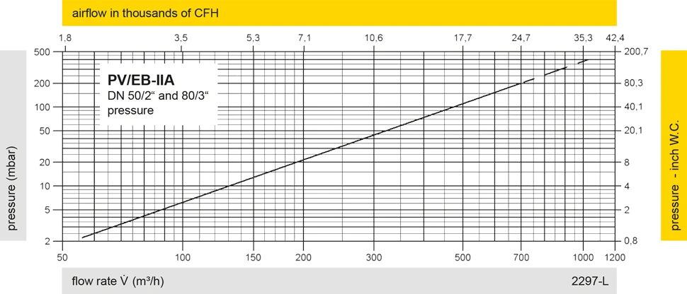
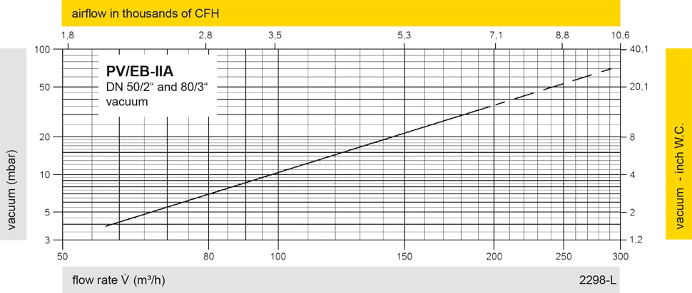
The flow capacity charts have been determined with a calibrated and TÜV certified flow capacity test rig. Volume flow V in (m³/h) and CFH refer to the standard reference conditions of air ISO 6358 (20°C, 1bar). For conversion to other densities and temperatures refer to Sec. 1: “Technical Fundamentals”.
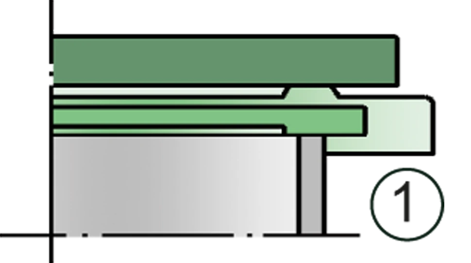
Detail X
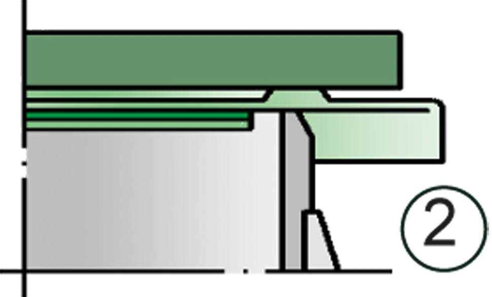
Detail X