DR/ES-PTFE
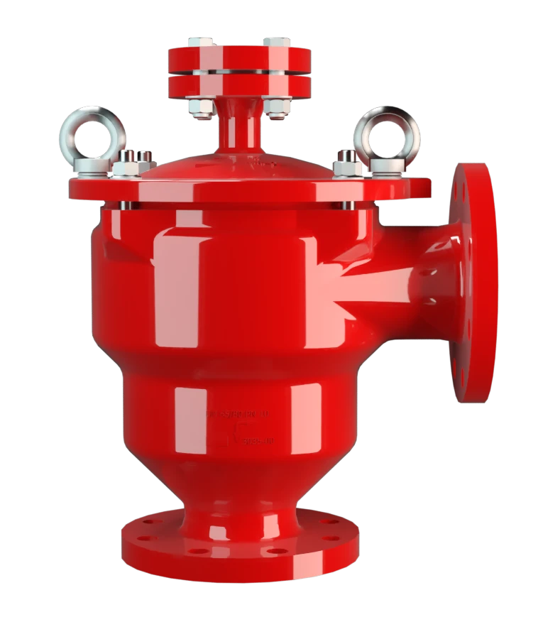
In-Line Detonation Flame Arrester for stable detonations and deflagrations in right angle design with shock absorber, unidirectional
Features
Reduced Number of FLAMEFILTER® Discs
Fastest Disassembly and Assembly
Modular Design
Explosion Safety
Angle Bodied
Low Costs
High-Tech Coating of the Housing
Main Component – PROTEGO® Flame Arrester Unit (PTFE)

For Explosion Group IIA
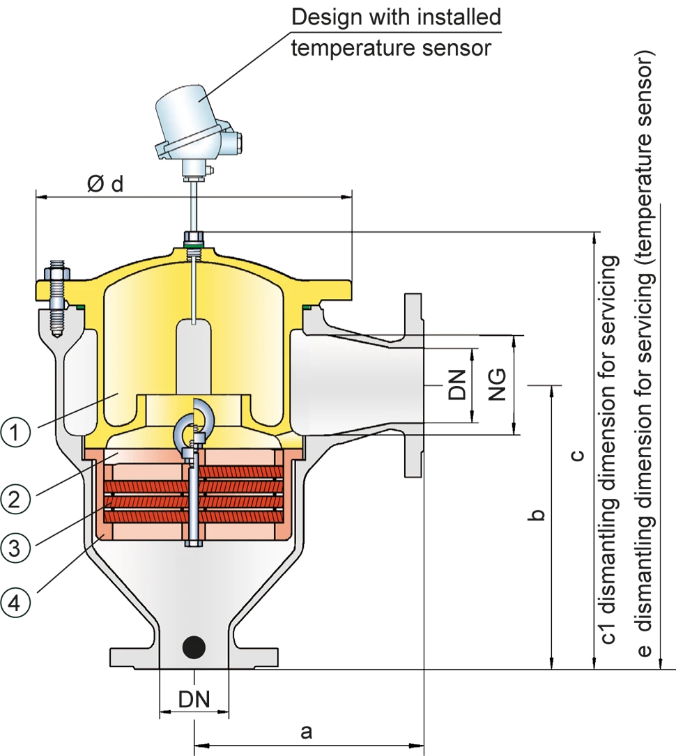
Dimensions
To select the nominal size (DN), please use the flow capacity charts on the following pages
| DN | 40 / 1½" | 50 / 2" | 65 / 2½" | 80 / 3" | 100 / 4" | 125 / 5" | 150 / 6" |
| a | 153 / 6.02 | 155 / 6.10 | 198 / 7.80 | 200 / 7.87 | 250 / 9.84 | 332 / 13.07 | 335 / 13.19 |
| b | 183 / 7.20 | 185 / 7.28 | 223 / 8.78 | 225 / 8.86 | 290 / 11.42 | 357 / 14.06 | 360 / 14.17 |
| c | 335 / 13.19 | 335 / 13.19 | 420 / 16.53 | 420 / 16.53 | 490 / 19.29 | 590 / 23.23 | 590 / 23.23 |
| c1 | 455 / 17.91 | 455 / 17.91 | 585 / 23.03 | 585 / 23.03 | 680 / 26.77 | 835 / 32.87 | 835 / 32.87 |
| d | 210 / 8.27 | 210 / 8.27 | 275 / 10.83 | 275 / 10.83 | 325 / 12.80 | 460 / 18.11 | 460 / 18.11 |
| e | 685 / 26.97 | 685 / 26.97 | 770 / 30.31 | 770 / 30.31 | 840 / 33.07 | 940 / 37.01 | 940 / 37.01 |
Dimensions in mm / inches
Selection of explosion group
| MESG | Expl. Gr. (IEC / CEN) | Gas Group (NEC) |
| > 0,90 mm | IIA | D |
Special approvals upon request
Selection of max. operating pressure
| DN | 40 / 1 ½" | 50 / 2" | 65 / 2 ½" | 80 / 3" | 100 / 4" | 125 / 5" | 150 / 6" | ||
| Expl. Gr. | IIA | Pmax | 1.1 / 15.9 | 1.1 / 15.9 | 1.2 / 17.4 | 1.2 / 17.4 | 1.1 / 15.9 | 1.1 / 15.9 | 1.1 / 15.9 |
Pmax = Maximum allowable operating pressure in bar / psi absolut, higher operating pressure upon request
Specification of max. operating temperature
| ≤ 60°C / 140°F | Tmaximum allowable operating temperature in °C |
| - | Designation |
higher operating temperatures upon request
Material selection for housing
| Design | A |
| Housing | Steel with an ECTFE coating |
| Cover with shock absorber | Steel with an ECTFE coating |
| Gasket | PTFE |
| Flame arrester unit | A, B, C |
Special materials upon request
Material combinations of flame arrester unit
| Design | A | B | C |
| FLAMEFILTER® cage | PTFE* | Hastelloy | Stainless Steel |
| FLAMEFILTER®* | PTFE* | PTFE* | PTFE* |
| Spacer | PEEK / ETFE / FEP | PEEK / ETFE / FEP | PEEK / ETFE / FEP |
*electrically conductive
Flange connection type
| EN 1092-1; Form B1 |
| ASME B16.5 CL 150 R.F. |
other connections upon request
Flow Capacity Chart
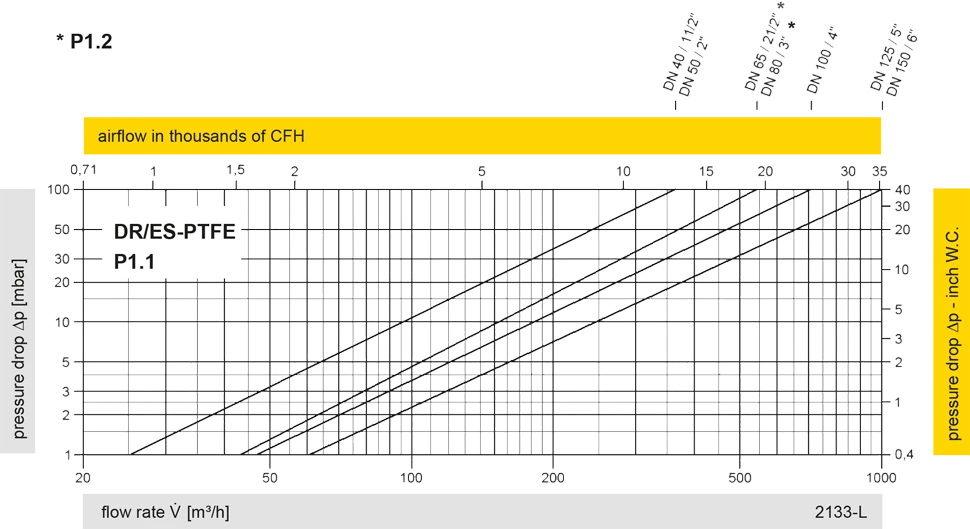
The flow capacity charts have been determined with a calibrated and TÜV certified flow capacity test rig. Volume flow V in (m³/h) and CFH refer to the standard reference conditions of air ISO 6358 (20°C, 1bar). For conversion to other densities and temperatures refer to Sec. 1: “Technical Fundamentals”.