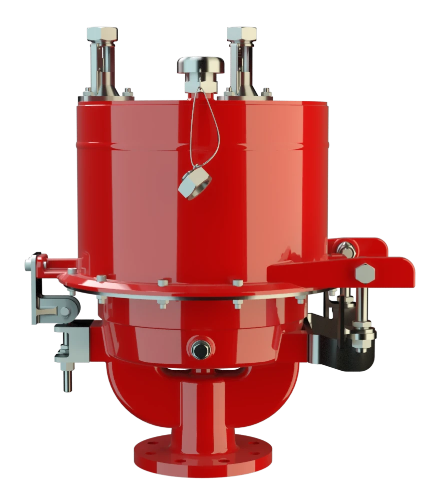
UB/SF
Pressure/Vacuum Diaphragm Valve deflagration- and endurance burning-proof
Features
Extreme Tightness
Optimal Pressure Maintenance
Flow Capacity
Digital Level Monitoring
Digital Level Sensors
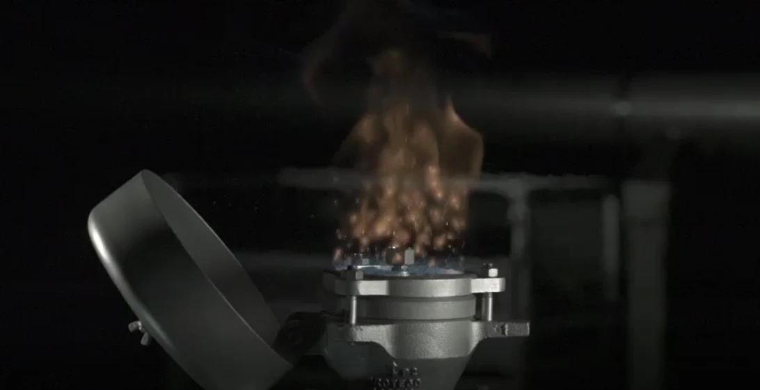
Safe Venting
Frost-Proof
Condensate Drainage
Monitoring
Modular Design
Suitable for Challenging Applications
Easy Operation Monitoring
Protective System According to ATEX
Safety Against Endurance Burning
Combined Pressure and Vacuum Relief Valve
For Explosion Group IIB3
Composition
Advanced Manufacturing Technology
Dynamic Flame Arresting Under Overpressure Conditions
Main Component – PROTEGO® Flame Arrester Unit
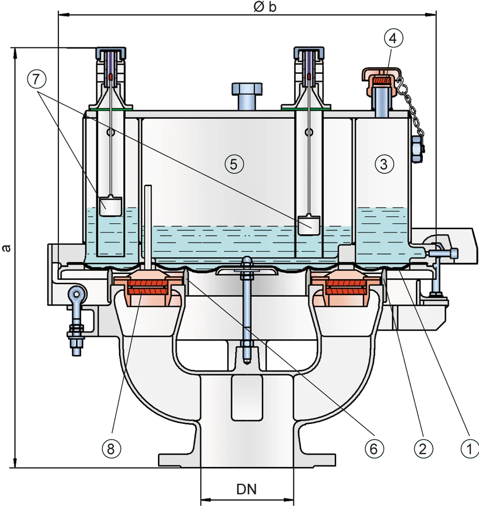
Dimensions
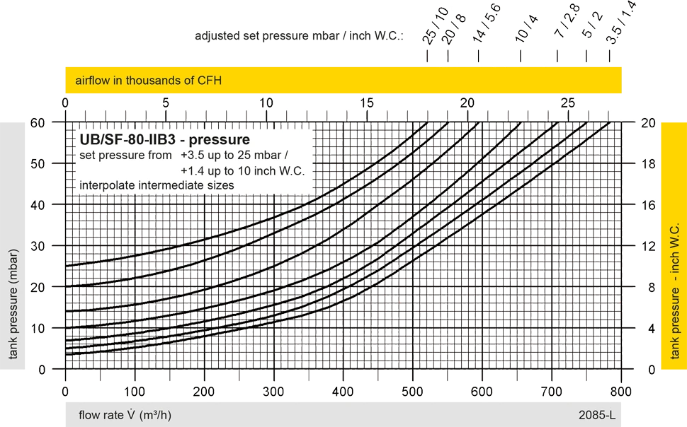
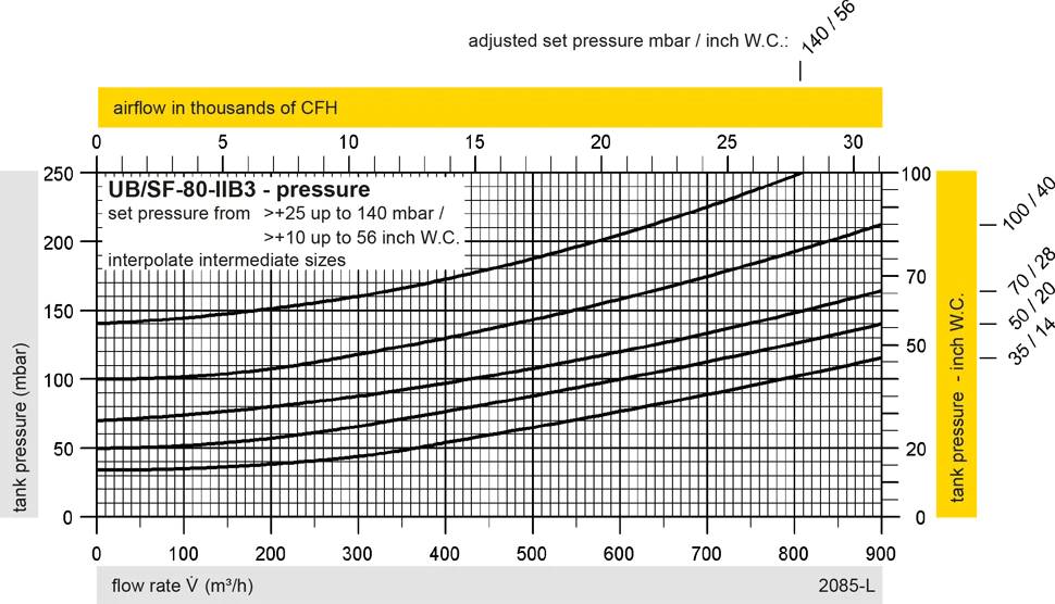
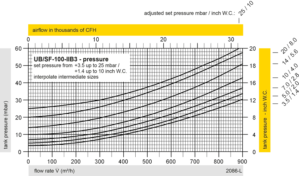
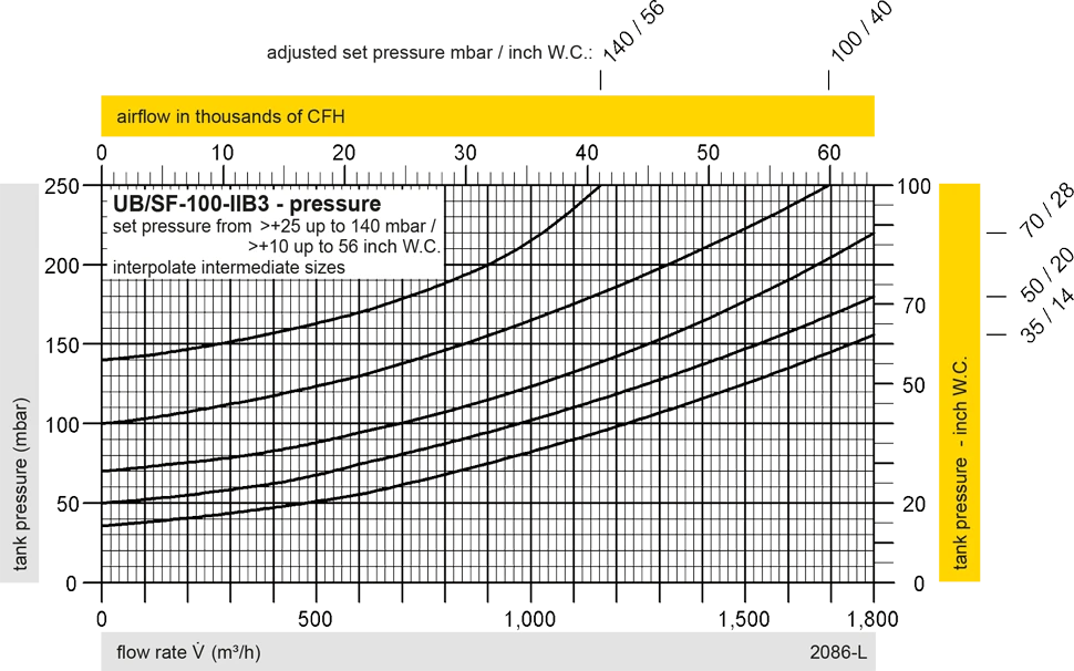
To select the nominal size (DN), please use the flow capacity charts on the following pages
| DN | pressure | pressure | 80 / 3" | pressure | pressure | 100 / 4" | pressure | pressure | 150 / 6" |
| a | up to +28 mbar | up to +11.2 inch W.C. | 615 / 24.21 | up to +28 mbar | up to +11.2 inch W.C. | 645 / 25.39 | up to +25 mbar | up to +10 inch W.C. | 680 / 26.77 |
| a | > +28 mbar | > +11.2 inch W.C. | 765 / 30.12 | > +28 mbar | > +11.2 inch W.C. | 795 / 31.30 | > +25 mbar | > +10 inch W.C. | 830 / 32.68 |
| b | 410 / 16.14 | 485 / 19.09 | 590 / 23.23 |
Dimensions in mm / inches
Pressure settings > +50 mbar / +20 inch W.C. (DN 80/3”), > +45 mbar / +18 inch W.C. (DN 100/4”), > +46 mbar / +18.4 inch W.C. (DN150/6”) with additional liquid reservoir - dimensions upon request
Dimensions for pressure/vacuum diaphragm valves with heating coil upon request
Selection of explosion group
| MESG | Expl. Gr. (IEC / CEN) | Gas Group (NEC) |
| ≥ 0,65 mm | IIB3 | C |
Special approvals upon request
Material selection for housing
| Design | C | D |
| Housing | Steel | Stainless Steel |
| Valve top | Stainless Steel | Stainless Steel |
| Heating coil (UB / SF-H-...) | Stainless Steel | Stainless Steel |
| Valve seat | Stainless Steel | Stainless Steel |
| Gasket | FPM | PTFE |
| Diaphragm | A, B | A, B |
| Flame arrester unit | C | C |
Option: Housing with ECTFE-lining
Special materials upon request
Material selection
| Design | A | B |
| Diaphragm | FPM | FEP |
Special materials upon request
Material combinations of flame arrester unit
| Design | C |
| FLAMEFILTER® cage | Stainless Steel |
| FLAMEFILTER® | Stainless Steel |
| Spacer | Stainless Steel |
Special materials upon request
Flange connection type
| EN 1092-1; Form B1 |
| ASME B16.5 CL 150 R.F. |
other types upon request
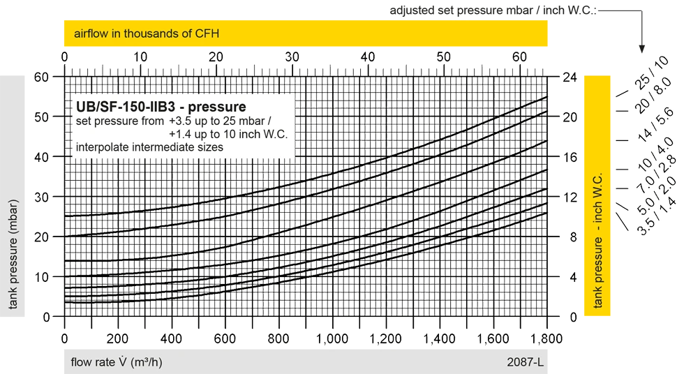
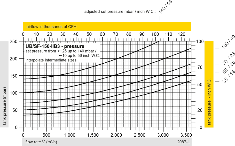
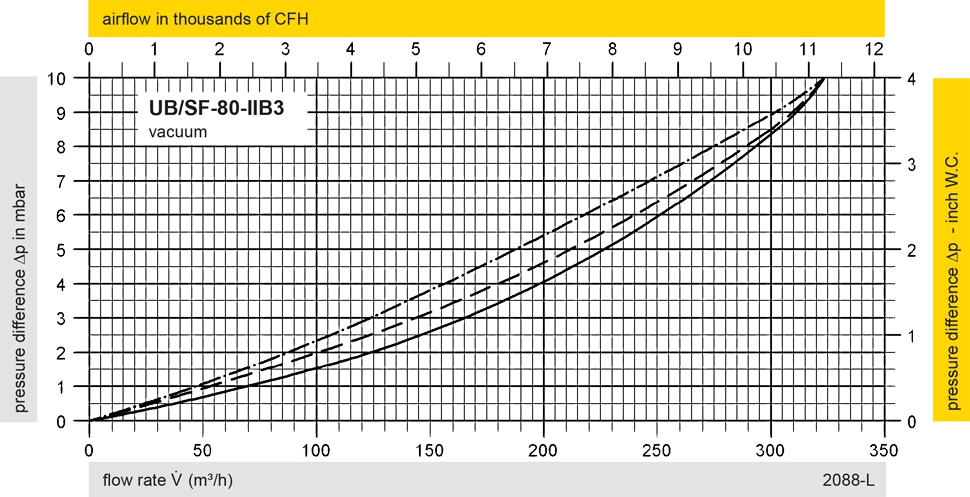
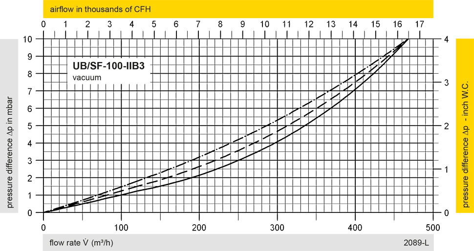
Flow Capacity Chart
UB/SF DN100 Pressure
UB/SF DN150 Pressure
UB/SF DN80 Vacuum
UB/SF DN100 Vacuum
UB/SF DN150 Vacuum
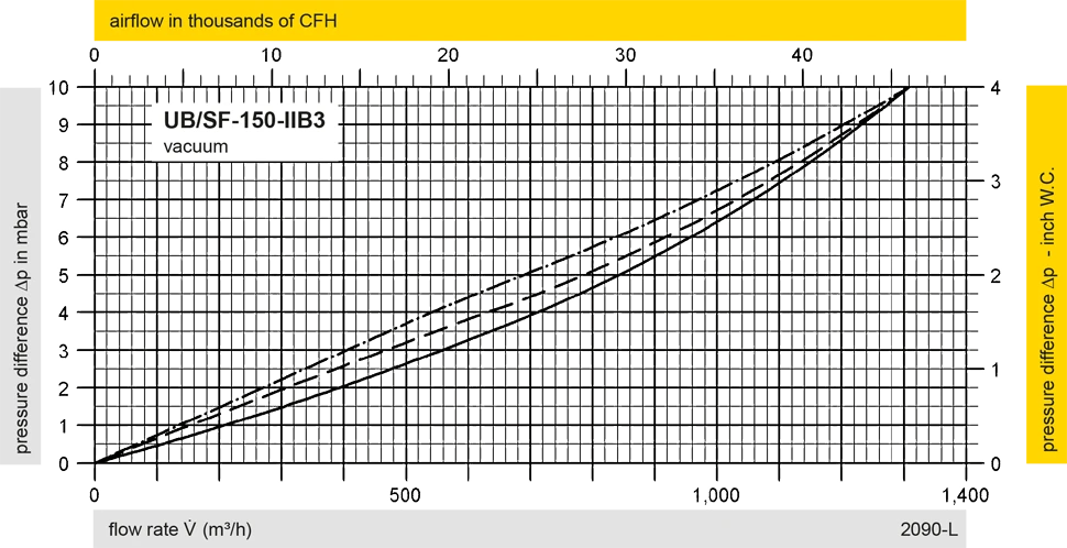
The flow capacity charts have been determined with a calibrated and TÜV certified flow capacity test rig. Volume flow V in (m³/h) and CFH refer to the standard reference conditions of air ISO 6358 (20°C, 1bar). For conversion to other densities and temperatures refer to Sec. 1: “Technical Fundamentals”.