BE/HK-E-IIB1
Deflagration Flame Arrester, endurance burning proof, End-of-Line

Features
Comprehensive Weather Protection
Weather Hood With Protection Screen Protects the PROTEGO® Flame Arrester Unit Against Environmental Impact, Such as Nesting Animals and Weather Conditions
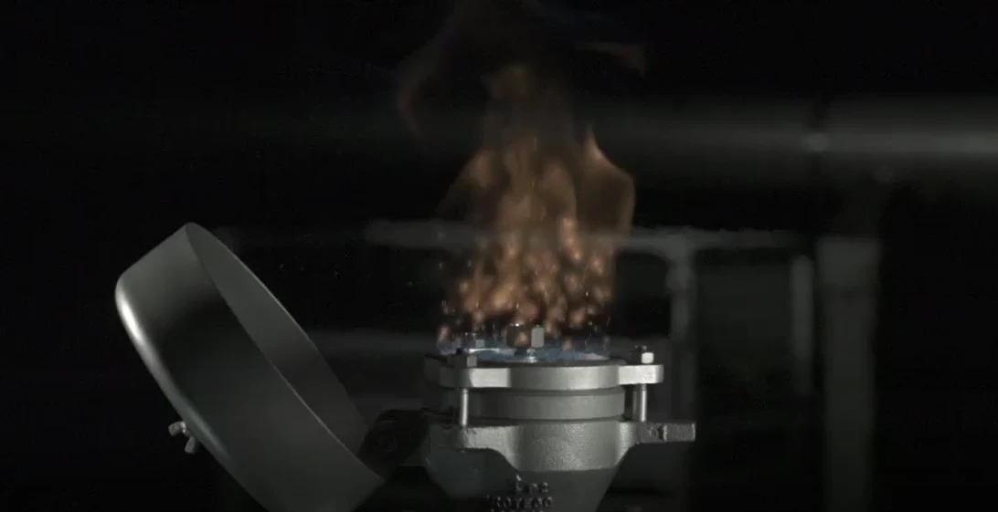
Visible Fire Indication by Tilting Weather Hood
in Case of Fire, the Weather Hood Opens, Allowing the Flame to Be Seen From a Far Distance
Spare Parts
Cost-Effective Spare Parts
Chemically Resistant
Centrally Aligned Melting Element Is Resistant to Chemicals
Endurance Burn Safety
for Alcohols and Hydrocarbons up to Explosion Group IIB
Modular Design
Allows Replacement and Cleaning of Single FLAMEFILTER®
Function and Description
Protection of Ethanol and Alcohols in Non-Pressurized Systems and Containers
The PROTEGO® BE/HK-E End-of-Line Deflagration Flame Arrester was specifically developed for vessels which are not pressurized and store ethanol or other alcohols. The combustion of alcohol requires a modified Flame Arrester Element design to provide protection against endurance burning. In addition, the device provides protection against atmospheric deflagration. It is typically installed on in-breathing and out-breathing vent lines to prevent flame transmission into the vessel or plant caused by endurance burning or atmospheric deflagration.
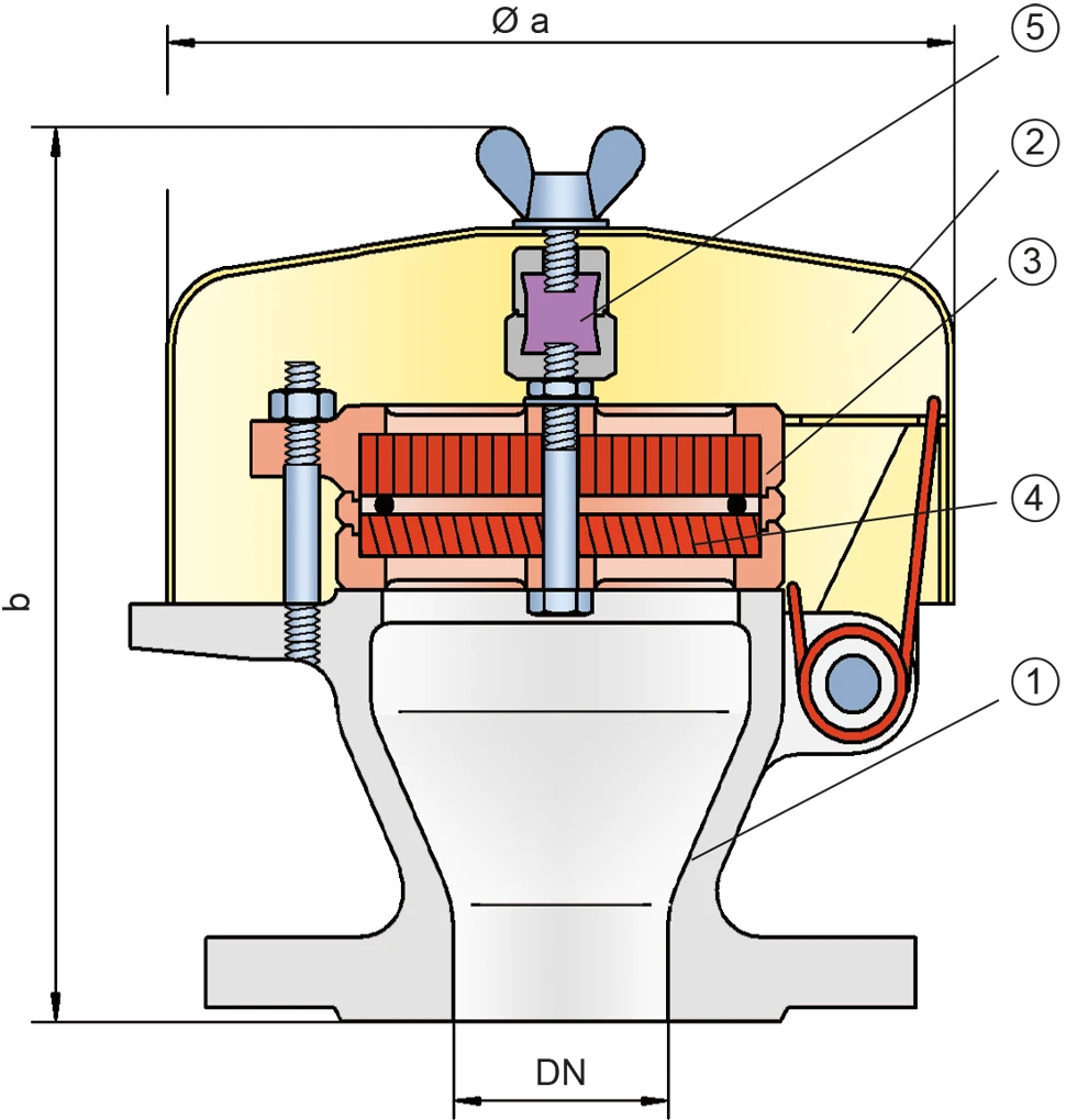
Main Component – PROTEGO® Flame Arrester Unit
The PROTEGO® BE/HK-E consists of the housing (1), a weather hood (2), and the PROTEGO® Flame Arrester Unit (3). During normal operation, the metal weather hood is in a closed position. If a stabilized flame burns on the Flame Arrester Element surface, the melting element (5), located in a center position, will melt, and the spring-loaded weather hood will open. The PROTEGO® Flame Arrester Unit consists of two FLAMEFILTER® discs (4) which are installed in a FLAMEFILTER® casing.

For Explosion Group IIB1
The PROTEGO® BE/HK-E End-of-Line Deflagration Flame Arrester is available for alcohols and other substances with MESG ≥ 0,85mm.
The standard design can be used for operating temperatures up to +60°C / 140°F.
EU conformity according to the currently valid ATEX directive. Approvals according to other national/international regulations on request.
Product Data
Dimensions
To select the nominal size (DN), please use the flow capacity charts on the following pages
| DN | 20 / ¾" | 25 / 1" | 32 / 1¼" | 40 / 1½" | 50 / 2" | 65 / 2½" | 80 / 3" |
| a | 163 / 6.42 | 163 / 6.42 | 163 / 6.42 | 183 / 7.20 | 183 / 7.20 | 218 / 8.58 | 218 / 8.58 |
| b | 180 / 7.09 | 177 / 6.97 | 177 / 6.97 | 190 / 7.48 | 190 / 7.48 | 200 / 7.87 | 200 / 7.87 |
Dimensions in mm / inches
Dimensions for deflagration flame arrester with heating jacket upon request
Selection of explosion group
| MESG | Expl. Gr. (IEC / CEN) | Gas Group (NEC) |
| ≥ 0,85 mm | IIB1 | – |
Special approvals upon request
Material selection for housing
| Design | B | C |
| Housing | Steel | Stainless Steel |
| Weather Hood | Steel | Stainless Steel |
| Flame arrester unit | A | A, B |
Special materials upon request
Material combinations of flame arrester unit
| Design | A | B |
| FLAMEFILTER® cage | Stainless Steel | Stainless Steel |
| FLAMEFILTER® | Stainless Steel | Hastelloy |
| Spacer | Stainless Steel | Hastelloy |
Special materials upon request
Flange connection type
| EN 1092-1; Form B1 |
| ASME B16.5 CL 150 R.F. |
other connections upon request
Flow Capacity Chart
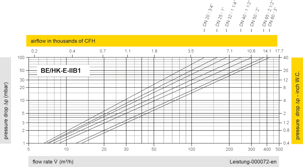
The flow capacity charts have been determined with a calibrated and TÜV certified flow capacity test rig. Volume flow V in (m³/h) and CFH refer to the standard reference conditions of air ISO 6358 (20°C, 1bar). For conversion to other densities and temperatures refer to Sec. 1: “Technical Fundamentals”.