ER/V-F
Pressure Relief Valve

Features
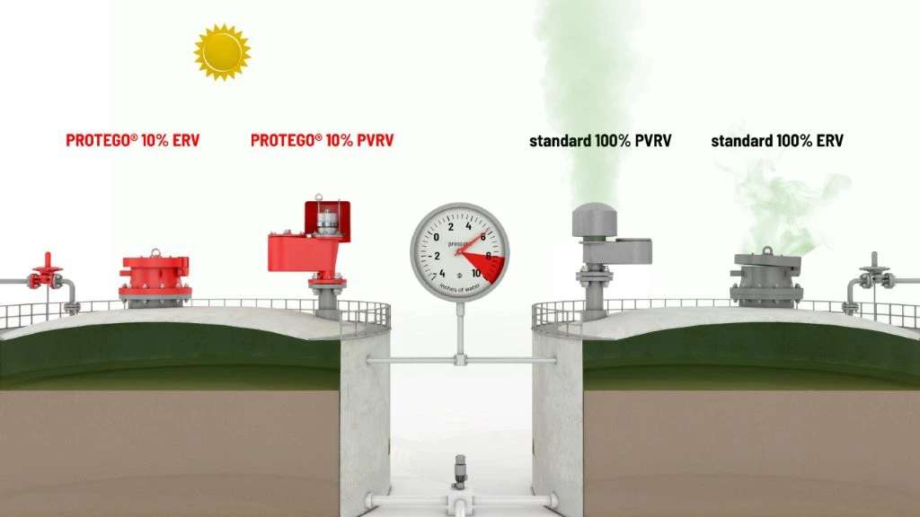
10% Technology
for Minimum Pressure Increase up to Full Lift
Extreme Tightness
Resulting in Lowest Possible Product Losses and Reduced Environmental Pollution
Optimal Pressure Maintenance
Set Pressure Close to Opening Pressure for Optimum Pressure Maintenance in the System
Flow Capacity
Optimized Flow Capacity
Guided Valve Pallet
Valve Pallet Is Guided Inside the Housing to Protect Against Harsh Weather Conditions
Used in Explosion Hazardous Areas
can Be Used in Explosion Hazardous Areas
Sturdy Housing Design
(PN 10 and PN 16)
Spring-Loaded
for High Set Pressures
API Tanks
Best Technology for API Tanks
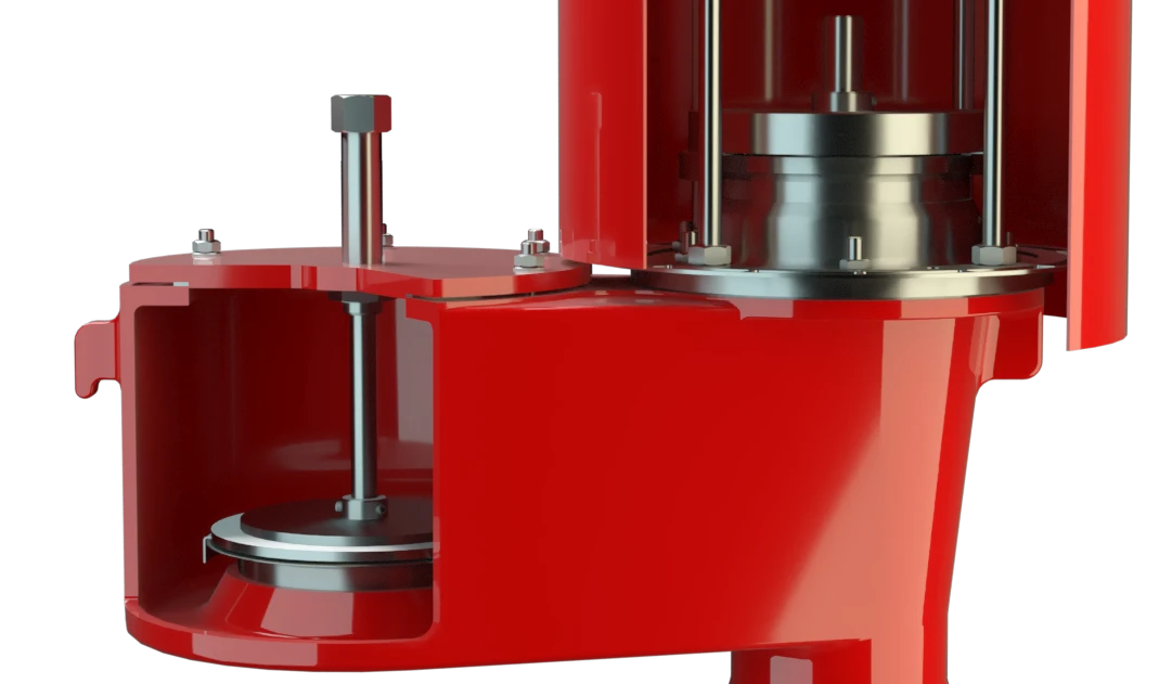
Function and Description
Highly Developed Pressure Relief Valve
The ER/V-F Type PROTEGO® valve is a highly developed emergency pressure relief valve with high flow capacity. It is primarily used as a device for emergency pressure relief for storage tanks, containers, silos, and process engineering equipment. It offers reliable protection against overpressure and prevents excessive product vapor loss close to the set pressure. It is designed to release particularly large amounts to prevent the vessel from rupturing in an emergency case. The springloading allows for higher set pressures than those with the ER-V-LP, ER/V, or ER/VH.
Full Lift Technology
The device will start to open as soon as the set pressure is reached and only requires 10% overpressure to reach full lift. Continuous investments in and a commitment to research and development have allowed PROTEGO® to develop a low pressure valve which has the same opening characteristic as a high pressure safety relief valve. This “Full Lift Type” technology allows the valve to be set at just 10% below the maximum allowable working pressure of the tank and still safely vent the required mass flow.
Advanced Manufacturing Technology
Due to the highly developed manufacturing technology, the tank pressure is maintained up to the set pressure with a tightness that is far superior to the conventional standard. This feature is achieved by valve seats made of high-grade steel with an inserted O-ring seal, a precisely lapped valve pallet, and a sturdy housing design. After the excess pressure is released, the valve re-seats and provides a tight seal again.
Product Data
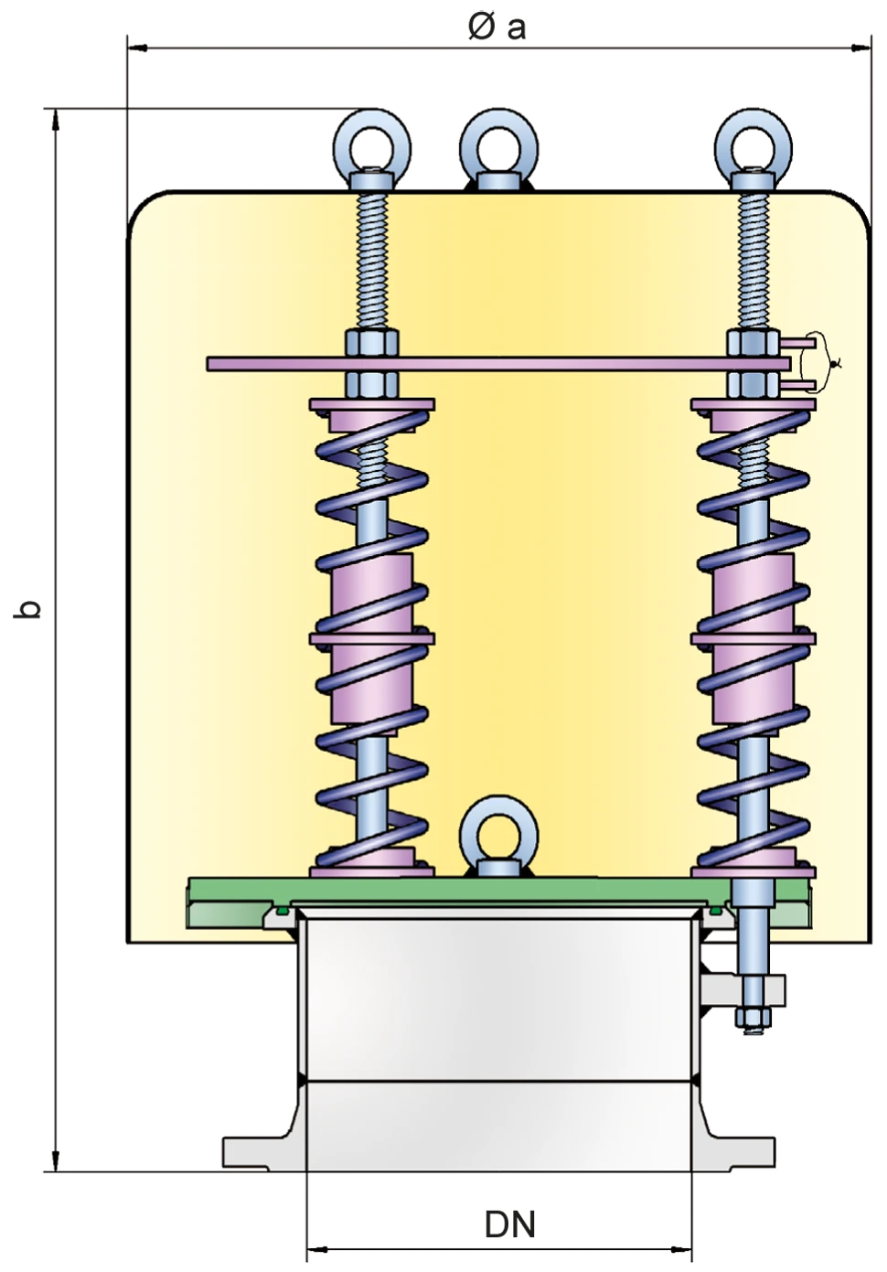
Dimensions
To select the nominal size (DN), use the flow capacity chart on the following page
| DN | 200 / 8" | 250 / 10" | 300 / 12" | 350 / 14" | 400 / 16" | 450 / 18" | 500 / 20" | 600 / 24" | 700 / 28" |
| a | 465 / 18.31 | 550 / 21.65 | 650 / 25.59 | 650 / 25.59 | 800 / 31.50 | 800 / 31.50 | 1000 / 39.37 | 1000 / 39.37 | 1200 / 47.24 |
| b | 860 / 33.86 | 860 / 33.86 | 1170 / 46.06 | 1170 / 46.06 | 1150 / 45.28 | 1175 / 46.26 | 1430 / 56.30 | 1425 / 56.10 | 1690 / 66.54 |
| (≤370 mbar) | (≤240 mbar) | (≤240 mbar) | (≤270 mbar) | (≤220 mbar) | (≤170 mbar) | (≤130 mbar) | (≤140 mbar) | (≤140 mbar) | |
| (≤148 inchW.C.) | (≤96 inchW.C.) | (≤96 inchW.C.) | (≤108 inchW.C.) | (≤88 inchW.C.) | (≤68 inchW.C.) | (≤52 inchW.C.) | (≤56 inchW.C.) | (≤56 inchW.C.) | |
| b | 980 / 38.58 | 980 / 38.58 | 1490 / 58.66 | 1490 / 58.66 | 1490 / 58.66 | 1515 / 59.65 | 1660 / 65.35 | 1655 / 65.16 | 1910 / 75.20 |
| (>370 mbar) | (>240 mbar) | (>240 mbar) | (>270 mbar) | (>220 mbar) | (>170 mbar) | (>130 mbar) | (>140 mbar) | (>140 mbar) | |
| (>148 inchW.C.) | (≤96 inchW.C.) | (≤96 inchW.C.) | (≤108 inchW.C.) | (≤88 inchW.C.) | (≤68 inchW.C.) | (≤52 inchW.C.) | (≤56 inchW.C.) | (≤56 inchW.C.) |
Dimensions in mm / inches
Material selection
| Design | A | B |
| Housing | Steel | Stainless Steel |
| Valve seat | Stainless Steel | Stainless Steel |
| Valve pallet | Stainless Steel or Steel-Stainless Steel | Stainless Steel |
| Sealing | FPM | FPM |
| Weight | Steel | Stainless Steel |
Special materials upon request
Flange connection type
| EN 1092-1; Form B1 |
| ASME B16.5 CL 150 R.F. |
other types upon request
Flow Capacity Chart
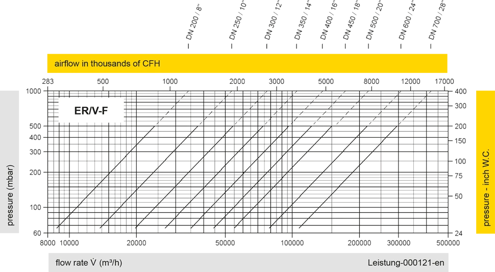
The flow capacity charts have been determined with a calibrated and TÜV certified flow capacity test rig. Volume flow V in (m³/h) and CFH refer to the standard reference conditions of air ISO 6358 (20°C, 1bar). For conversion to other densities and temperatures refer to Sec. 1: “Technical Fundamentals”.