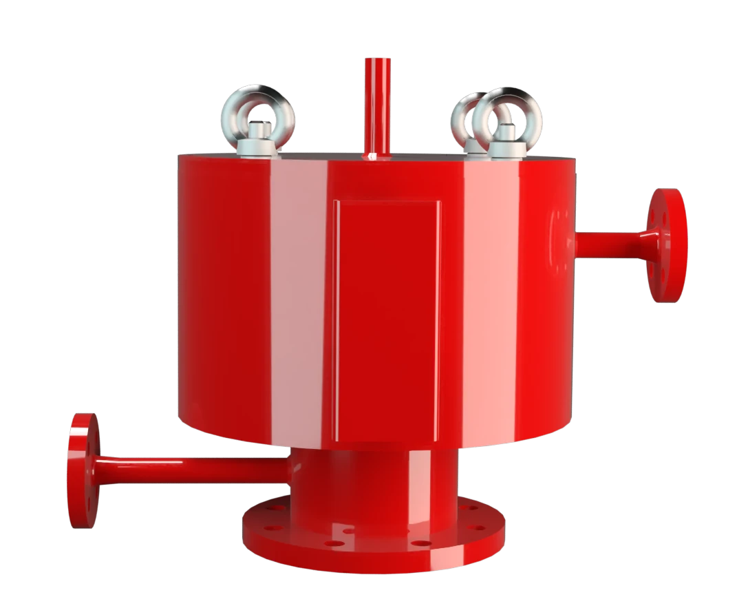
SD/BS-H
Pressure Relief Valve in heat jacketed design
Features
Tecnología del 10%
para un aumento mínimo de presión hasta alcanzar la apertura completa
Camisas de calefacción
Camisa de calefacción completa hasta la brida para evitar la acumulación de hielo
Temperatura del fluido portador de calor
Temperatura máxima permitida del medio calefactable de 320 °C / 608 °F (a 6 bar / 87 psi)
Tapa de válvula calefactable disponible
Disponible en un diseño especial con tapa de válvula calefactable
Diseño de cuerpo robusto
(PN 10 & PN 16)
Se usa en zonas con riesgo de explosión
Puede utilizarse en zonas con riesgo de explosión
Extrema estanqueidad
Lo que se traduce en las menores pérdidas posibles de producto y en una reducción de la contaminación ambiental
Mantenimiento óptimo de la presión
Presión de tarado próxima a la presión de apertura para un mantenimiento óptimo de la presión en el sistema
Flujo volumétrico
Flujo de caudal optimizado
Plato de válvula guiado
El plato de válvula va guiado dentro del cuerpo para protegerlo frente a condiciones meteorológicas adversas
Function and Description
Highly Developed Pressure Relief Valve
The SD/BS-H Type PROTEGO® valve is a highly developed pressure relief valve with a heating jacket down to the flange. It is primarily used as pressure relief device for vessels and process engineering equipment under difficult operating conditions. This includes extreme weather conditions or products that tend to form polymers at certain temperatures, stick together, or form deposits that negatively influence function (such as bitumen, tar, dust). The valve offers reliable protection against overpressure and prevents excessive loss of product vapors close to the set pressure.
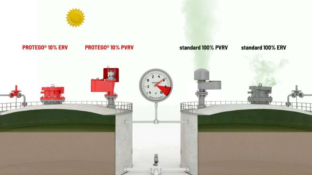
Full Lift Technology
The device will start to open as soon as the set pressure is reached and only requires 10% overpressure to full lift. Continuous investments in and a commitment to research and development have allowed PROTEGO® to develop a low pressure valve which has the same opening characteristic as a high pressure safety relief valve. With this “Full Lift Type” technology, the valve can be set at just 10% below the maximum allowable working pressure of the tank and still safely vent the required mass flow.
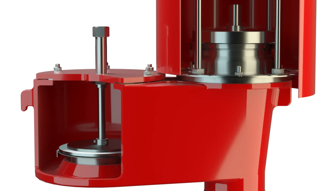
Advanced Manufacturing Technology
Due to our highly developed manufacturing technology, the tank pressure is maintained up to set pressure with a tightness that is far superior to the conventional standard. This feature is achieved by valve seats made of high-grade stainless steel with precisely lapped valve pallets and a sturdy housing design.After the excess pressure is released, the valve re-seats and provides a tight seal again.
Product Data
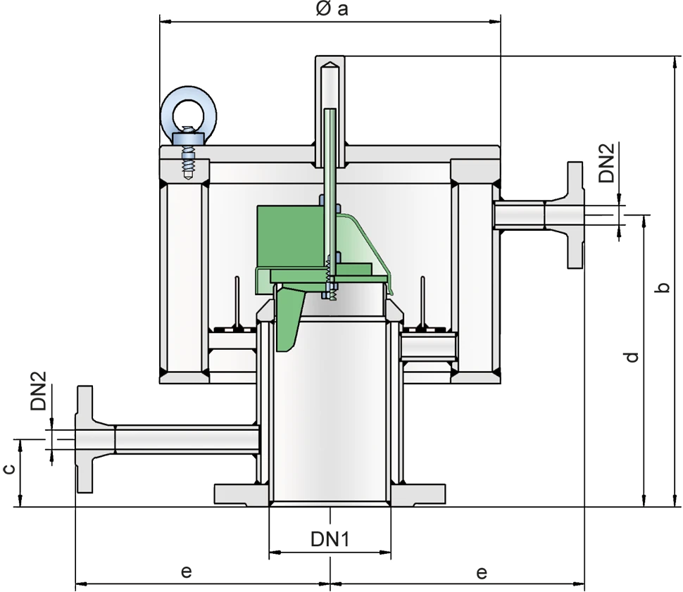
Dimensiones
To select the nominal size (DN), use the flow capacity chart on the following page
| DN1 | DN2 | a | b | b | c | d | d | e |
| bis 30 mbar | > 30 mbar | bis 30 mbar | > 30 mbar | |||||
| 80 / 3" | 15 / ½" | 325 / 12.80 | 400 / 15.75 | 515 / 20.28 | 70 / 2.76 | 250 / 9.84 | 390 / 15.35 | 250 / 9.84 |
| 100 / 4" | 15 / ½" | 325 / 12.80 | 400 / 15.75 | 505 / 19.88 | 60 / 2.36 | 250 / 9.84 | 380 / 14.96 | 250 / 9.84 |
| 150 / 6" | 15 / ½" | 405 / 15.94 | 460 / 18.11 | 595 / 23.43 | 60 / 2.36 | 315 / 12.40 | 470 / 18.50 | 290 / 11.42 |
| 200 / 8" | 15 / ½" | 510 / 20.08 | 470 / 18.50 | 575 / 22.64 | 65 / 2.56 | 305 / 12.01 | 445 / 17.52 | 340 / 13.39 |
Dimensiones en mm / pulgadas
* also available with special flange DN 50 / 2''
Selección de materiales para la vivienda
| Design | A | B |
| Housing | Steel | Stainless Steel |
| Heating Jacket | Steel | Stainless Steel |
| Valve Seat | Stainless Steel | Stainless Steel |
Special materials upon request
Selección de materiales para la válvula de presión
| Design | A | B | C |
| Pressure range [mbar] [inch W.C.] | +5,0 up to +25 +2 up to +10 | >+10 up to +30 >+4 up to +12 | >+30 up to +210 >+12 up to +84 |
| Valve pallet | Aluminium | Stainless Steel | Stainless Steel |
| Valve pallet hood | Stainless Steel | Stainless Steel | - |
| Sealing | Metal to Metal | Metal to Metal | Metal to Metal |
Special materials and devices with higher set pressure or vacuum are available upon request
Tipo de bridas de conexión
| EN 1092-1; Form B1 |
| ASME B16.5 CL 150 R.F. |
other types upon request
Diagrama de flujo volumétrico
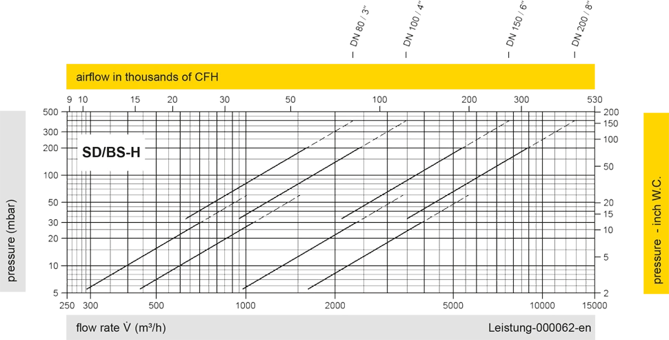
Los diagramas de flujo volumétrico han sido determinados con un banco de pruebas de caudal calibrado y certifi - cado por TÜV. El flujo volumétrico V. en [m³/h] y el CFH se refi eren a las condiciones estándar de referencia de aire según ISO 6358 (20°C, 1bar). La conversión a otras densidades y temperaturas están referidas en el Vol. 1: “Fundamentos Técnicos”.