WV/T
Change-Over Valve
Features
Para tanques criogénicos
Apto para uso en tanques criogénicos
Superficies de sellado metálicas
Estanqueidad extremadamente alta gracias a las superficies de sellado metálicas
Industrias química y farmacéutica
En tanques de plantas de proceso de las industrias química, petroquímica y farmacéutica
Seguridad funcional y valores de rendimiento
Las válvulas se caracterizan por una alta fiabilidad de funcionamiento y unos excelentes valores de rendimiento
Rápida sustitución
Sustitución rápida de los elementos que afectan el funcionamiento
Válvulas y dispositivos de seguridad
Uso conjunto con válvulas u otros dispositivos de seguridad (por ejemplo, apagallamas PROTEGO®)
Function and Description
Operational Safety of Protected Plant Systems
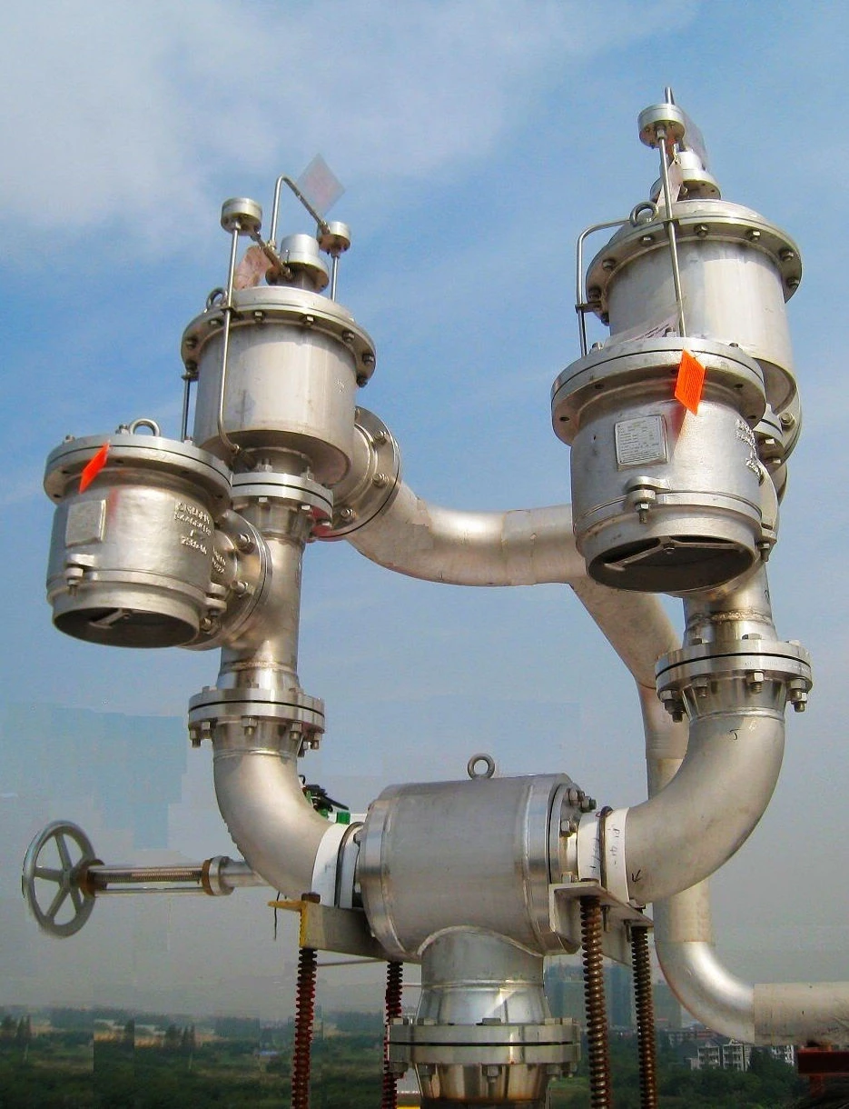
PROTEGO® WV/T Change-Over Valves are mainly used together with other valves or devices (e.g., PROTEGO® Flame Arresters) on cryogenic storage tanks and on tanks in process plants in the chemical, petrochemical, and pharmaceutical industries. They increase the operational safety of the equipment to be protected, as each valve or device can be checked, maintained, or repaired without interrupting plant operation.
Ensuring Performance Even with Large Temperature Differences
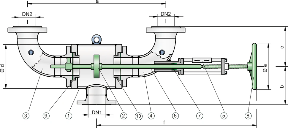
The valves mainly consist of the housing (1) with flange connections DN 1 and two lateral connection elbows (3, 4) with flange connections DN 2 and the valve disc (2). If necessary, it is possible to off-set and turn the connection elbows. The valve seats (9, 10) are replaceable. The valve disc with metallic sealing surface is movable on the valve spindle (6). This ensures good contact pressure with the valve seats (9, 10) even with high temperature differences. The sealing between the valve disc and valve spindle is done by an O-ring. The valve spindle is guided by bushings and sealed to the outside by an adjustable sealing set (7).
Flexible Operating Position with Change-Over Valve
The Change-Over Valves allows the operator to block one valve or device at a time by operating the hand wheel (8). In normal operation, the valve disc (2) is in middle position and the gas/liquid flows through both connection elbows. By turning the hand wheel as far as it will go, one of the connecting elbows (3 or 4) is closed while the other one remains open. The actual position of the valve disc is indicated by the position indicator (5) on the valve spindle.
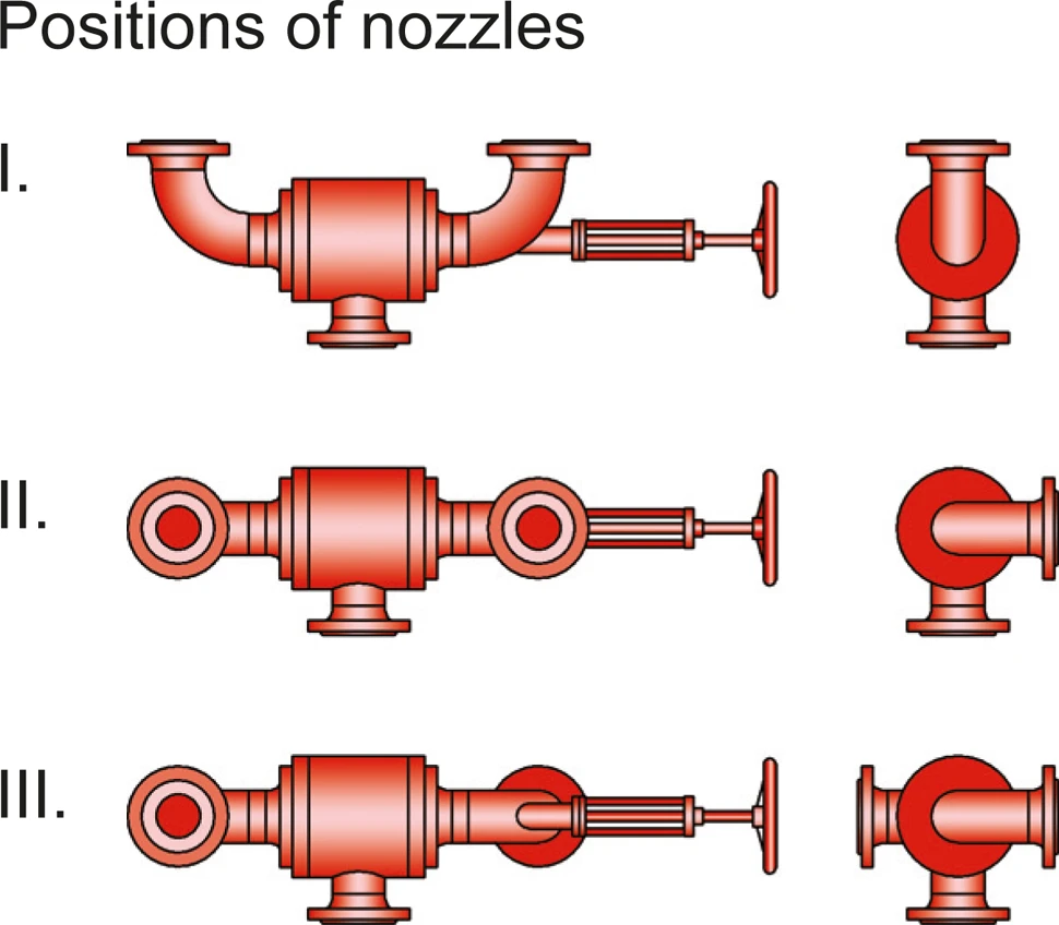
Depending on the requirements, the position of the change-over valve in normal operation can be in the middle or end position: Middle position, for example, is if a high capacity of relief is required through emergency relief valves controlled in parallel. End position, for example, is with flame arresters that are connected in parallel and can be used or cleaned alternately.
High Operational Reliability and Excellent Performance
Due to their design and appropriately selected materials, the valves are characterized by their high functional reliability and very good flow rates. All elements are made of stainless steel.
The design of the PROTEGO® WV/T Change-Over Valves allows the following connections to be made in accordance with the variable valve position or other devices with both angle or straight connections without additional fittings.
Use in Explosion-Hazard Areas
PROTEGO® WV/T Change-Over Valves are characterized by their simple design, easy handling, the option of quick replacement of components that affect the function, and by their excellent availability and operational reliability. The lapped metallic sealing surfaces ensure a high degree of tightness even in low temperature ranges.
These valves are not flame-proof and do not fall within the scope of the European Explosion Protection Directive 94/9/EC, even if installed in explosive atmospheres.
Based on a hazard analysis with regard to material selection and function, the valves have no potential ignition sources. This enables unrestricted use in potentially explosive areas.
Product Data
Dimensiones
| DN1 | 80 / 3" | 100 / 4" | 150 / 6" | 200 / 8" | 200 / 8" | 250 / 10" | 300 / 12" |
| DN2 | 80 / 3" | 100 / 4" | 150 / 6" | 150 / 6" | 200 / 8" | 250 / 10" | 300 / 12" |
| a | 780 / 30.71 | 780 / 30.71 | 960 / 37.80 | 960 / 37.80 | 1130 / 46.12 | 1450 / 57.09 | 1650 / 64.96 |
| b | 250 / 9.84 | 250 / 9.84 | 310 / 12.20 | 310 / 12.20 | 330 / 13.47 | 360 / 14.17 | 415 / 16.34 |
| c * | 303 / 11.93 | 205 / 8.07 | 285 / 11.22 | 285 / 11.22 | 367 / 14.98 | 450 / 17.72 | 525 / 20.67 |
| c ** | 323 / 12.72 | 230 / 9.06 | 317 / 12.48 | 317 / 12.48 | 407 / 16.02 | 483 / 19.01 | 571 / 22.48 |
| d | 273 / 10.75 | 273 / 10.75 | 324 / 12.76 | 324 / 12.76 | 355 / 14.49 | 457 / 17.99 | 500 / 19.68 |
| e | 250 / 9.84 | 250 / 9.84 | 250 / 9.84 | 250 / 9.84 | 400 / 16.33 | 400 / 15.75 | 500 / 19.68 |
| f | 905 / 35.63 | 905 / 35.63 | 1070 / 42.13 | 1070 / 42.13 | 1200 / 47.24 | 1530 / 60.24 | 1655 / 59.65 |
| fmin | 810 / 31.89 | 810 / 31.89 | 950 / 37.40 | 950 / 37.40 | 1080 / 42.52 | 1360 / 53.54 | 1470 / 57.87 |
| fmax | 995 / 39.17 | 995 / 39.17 | 1190 / 46.85 | 1190 / 46.85 | 1310 / 53.47 | 1695 / 66.73 | 2015 / 79.33 |
Dimensiones en mm / pulgadas
* for connection flange DIN PN16 resp. from DN 200 DIN PN 10
** for connection flange ANSI 150 lbs
Selección de materiales
| Design | A | B |
| Housing and connection elbows | Steel | Stainless Steel |
| Valve disc | Hastelloy | Hastelloy |
| Packing | PTFE | PTFE |
| Spindle sealing | FPM | FPM |
| Handwheel | Steel | Steel |
The connection flange material must be compatible to the material of the plant component. Special models of change-over valves are available for specific requirements.
Tipo de bridas de conexión
| EN 1092-1, Form B1 or DIN 2501, Form C, PN 16 , ab DN 200 PN 10 | EN or DIN |
| ASME B16.5 CL 150 R.F. | ASME |
Other types upon request