FA-CN-IIC
In-Line Deflagration Flame Arrester for hydrogen/air-mixtures, concentric design, bidirectional
Features
Piezas de recambio
Diseño compacto
Diseño modular
Transmisión bidireccional de la llama
Proporciona seguridad
Cualquier posición de instalación
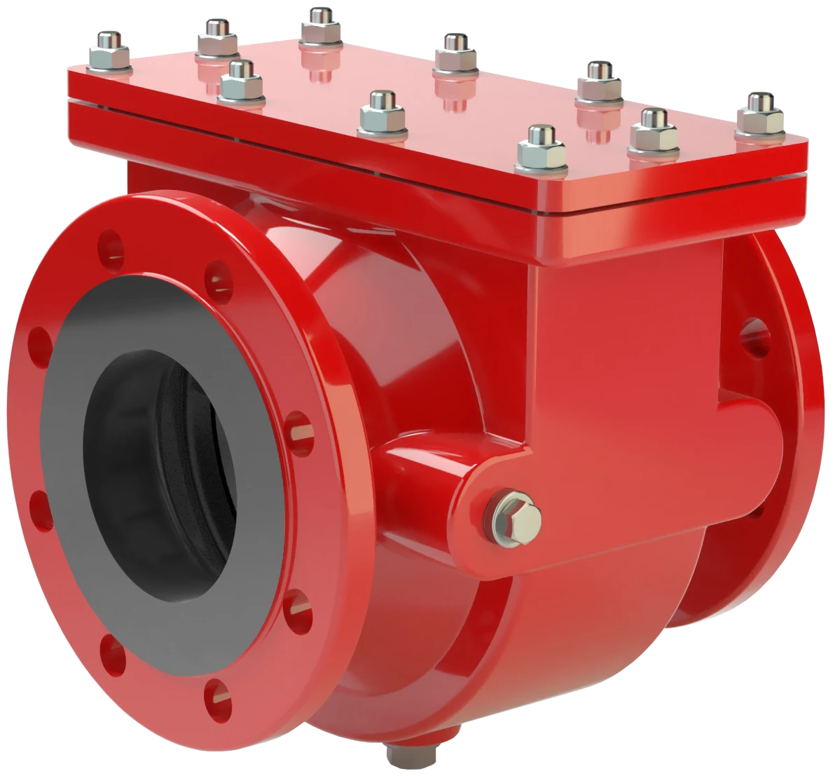
Compact and Maintenance-Friendly Design
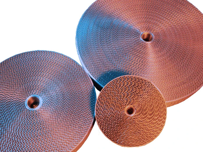
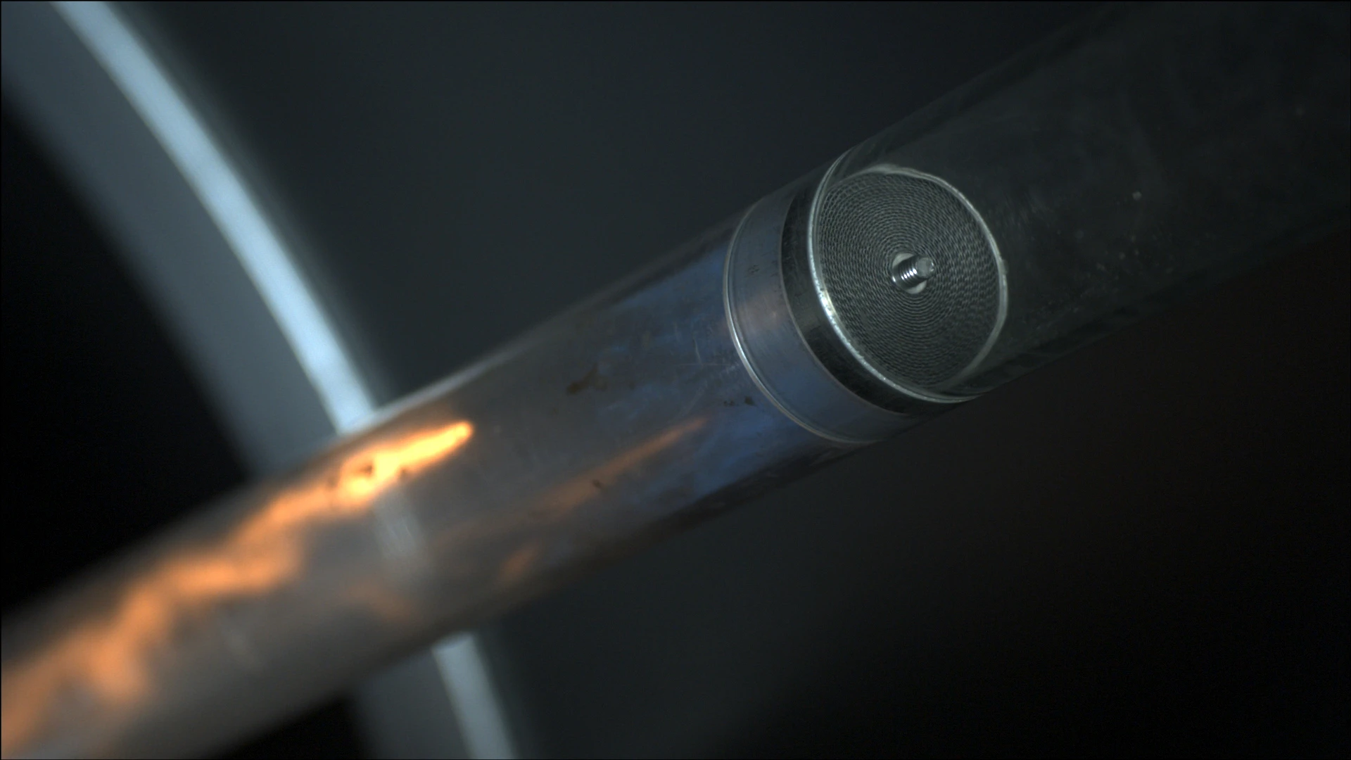
Main Component – PROTEGO® Flame Arrester Unit
For Explosion Group IIC

Many Individual Certifications
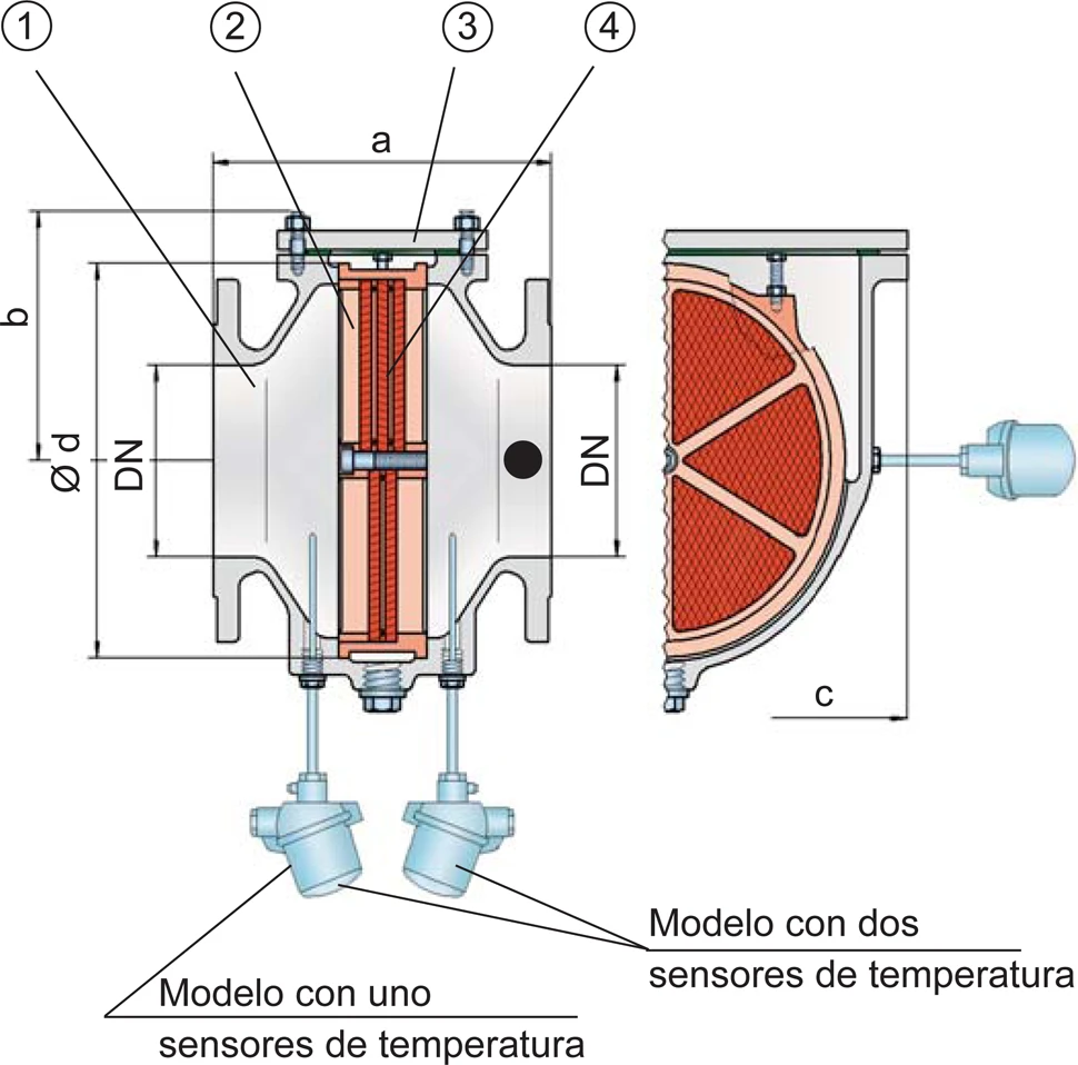
Dimensiones
To select the nominal size (DN), use the flow capacity charts on the following pages
| DN | 40 / 1½“ | 50 / 2“ | 65 / 2½“ | 80 / 3“ | 100 / 4“ | 125 / 5“ | 150 / 6“ | 200 / 8" | 250 / 10" | 300 / 12" |
| a | 210 / 8.27 | 215 / 8.46 | 235 / 9.25 | 240 / 9.45 | 265 / 10.43 | 305 / 12.01 | 310 / 12.20 | 300 / 11.81 | 320 / 12.60 | 350 / 13.78 |
| b | 105 / 4.13 | 105 / 4.13 | 132 / 5.2 | 132 / 5.2 | 150 / 5.91 | 197 / 7.75 | 197 / 7.75 | 220 / 8.66 | 260 / 10.24 | 295 / 11.61 |
| c | 200 / 7.87 | 200 / 7.87 | 260 / 10.24 | 260 / 10.24 | 308 / 12.13 | 415 / 16.34 | 415 / 16.34 | 446 / 17.56 | 520 / 20.47 | 600 / 23.62 |
| d | 130 / 5.12 | 130 / 5.12 | 185 / 7.28 | 185 / 7.28 | 220 / 8.66 | 310 / 12.20 | 310 / 12.20 | 355 / 13.98 | 420 / 16.54 | 490 / 19.29 |
Dimensiones en mm / pulgadas
Selección del grupo de explosión
| MESG | Expl. Gr. (IEC / CEN) | Gas Group (NEC) |
| < 0,50 mm | IIC | B |
Special approvals upon request
Selección de la máxima presión de operación
| DN | 40 / 1½" | 50 / 2" | 65 / 2½" | 80 / 3" | 100 / 4" | 125 / 5" | 150 / 6" | 200 / 8'' | 250 / 10'' | 300 / 12'' |
| Pmax | 1,1 / 15.9 | 1,1 / 15.9 | 1,1 / 15.9 | 1,1 / 15.9 | 1,1 / 15.9 | 1,1 / 15.9 | 1,1 / 15.9 | 1,1 / 15.9 | 1,1 / 15.9 | 1,1 / 15.9 |
Pmax = maximum allwowable operating pressure in bar / psi absolute, higher operating pressure upon request
Máx. radio L/D admisible
| DN | 40 / 1½" | 50 / 2" | 65 / 2½" | 80 / 3" | 100 / 4" | 125 / 5" | 150 / 6" | 200 / 8'' | 250 / 10'' | 300 / 12'' |
| (L / D)max | 30 | 30 | 10 | 10 | 10 | 20 | 20 | 10 | 10 | 5 |
| Designation | - | - | X12 | X12 | X12 | X10 | X10 | X12 | X12 | X13 |
Selección de materiales
| Design | A | B |
| Housing | Steel | Stainless Steel |
| Cover | Steel | Stainless Steel |
| Gasket | PTFE | PTFE |
| Flame arrester unit | Stainless Steel | Stainless Steel |
Special materials upon request
Tipo de bridas de conexión
| EN 1092-1; Form B1 |
| ASME B16.5 CL 150 R.F. |
other connections upon request
Diagrama de flujo volumétrico
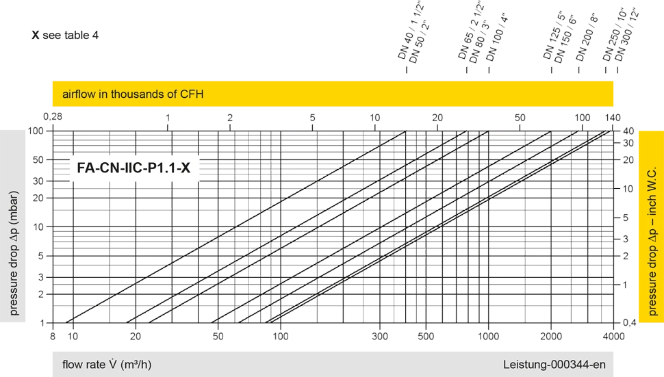
Los diagramas de flujo volumétrico han sido determinados con un banco de pruebas de caudal calibrado y certifi - cado por TÜV. El flujo volumétrico V. en [m³/h] y el CFH se refi eren a las condiciones estándar de referencia de aire según ISO 6358 (20°C, 1bar). La conversión a otras densidades y temperaturas están referidas en el Vol. 1: “Fundamentos Técnicos”.