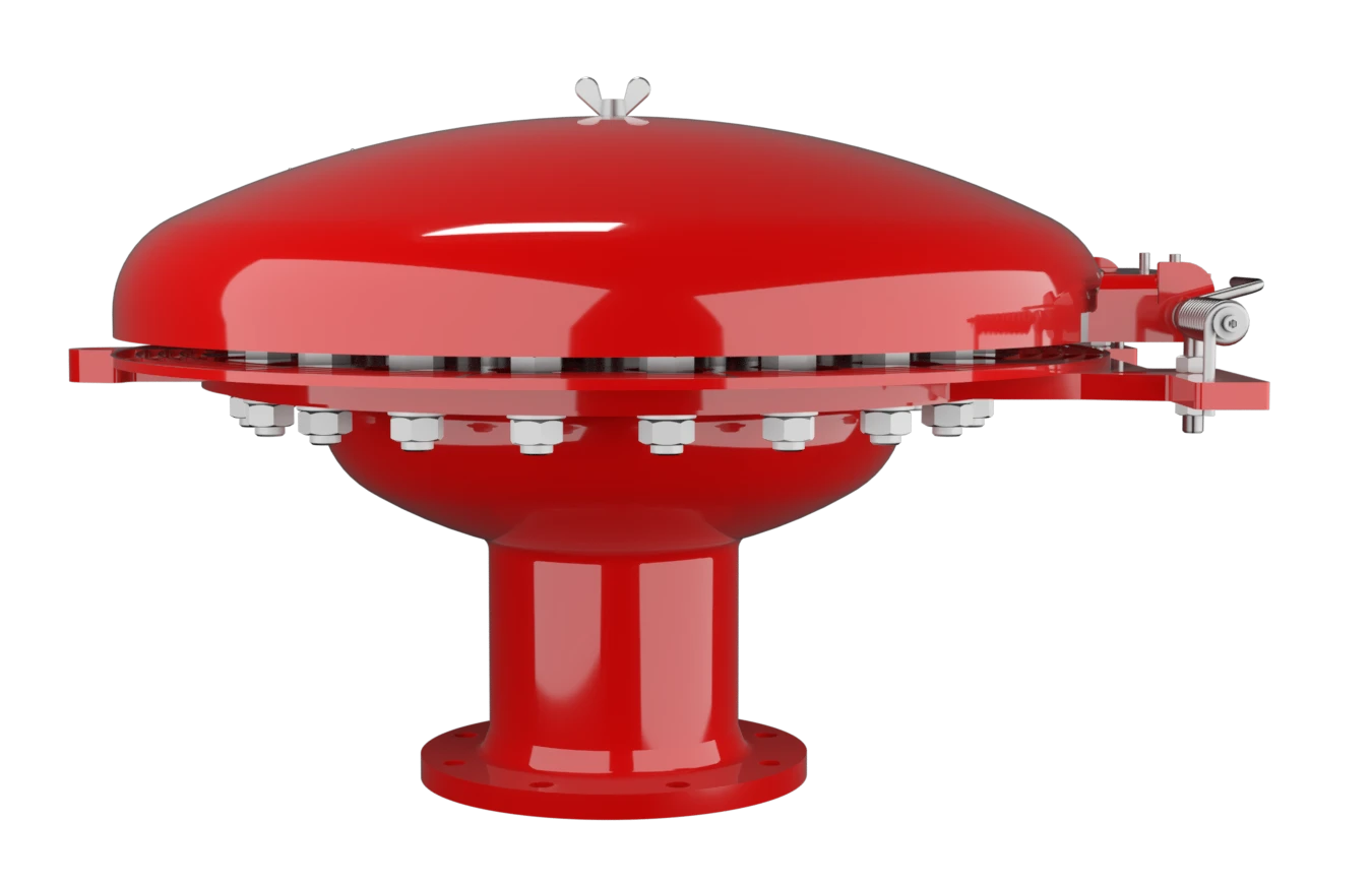
EB
Deflagration Flame Arrester, endurance burning proof, End-of-Line
Features
Protección integral contra la intemperie
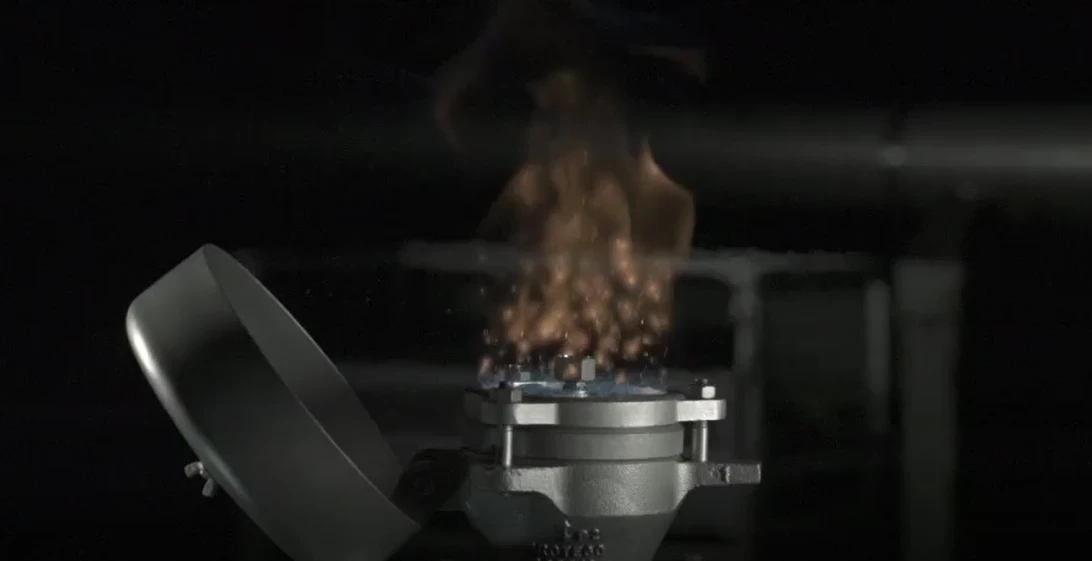
Indicación visible de fuego mediante inclinación de la caperuza protectora contra la intemperie
Seguridad frente a deflagraciones e incendios de hidrocarburos
Resistente a productos químicos
Diseño modular
Fácil mantenimiento
Piezas de recambio
Protection Against Atmospheric Deflagration and Endurance Burning
Main Component – PROTEGO® Flame Arrester Unit

For Explosion Group IIB and IIA
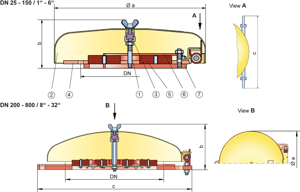
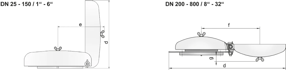
Dimensiones DN 25 - 150 para EB-IIA y IIB
To select the nominal size (DN), please use the flow capacity chart on the following page
| DN | 25 / 1" | 32 / 1¼“ | 40 / 1½“ | 50 / 2“ | 65 / 2½“ | 80 / 3“ | 100 / 4" | 125 / 5" | 150 / 6" |
| a | 218 / 8.58 | 218 / 8.58 | 218 / 8.58 | 218 / 8.58 | 218 / 8.58 | 353 / 13.90 | 353 / 13.90 | 353 / 13.90 | 353 / 13.90 |
| b | 113 / 4.45 | 113 / 4.45 | 113 / 4.45 | 113 / 4.45 | 113 / 4.45 | 113 / 4.45 | 113 / 4.45 | 113 / 4.45 | 113 / 4.45 |
| c | 232 / 9.13 | 232 / 9.13 | 232 / 9.13 | 232 / 9.13 | 232 / 9.13 | 306 / 12.05 | 306 / 12.05 | 306 / 12.05 | 306 / 12.05 |
| d | 222 / 8.74 | 222 / 8.74 | 222 / 8.74 | 222 / 8.74 | 222 / 8.74 | 355 / 13.98 | 355 / 13.98 | 355 / 13.98 | 355 / 13.98 |
| e | 217 / 8.54 | 217 / 8.54 | 217 / 8.54 | 217 / 8.54 | 217 / 8.54 | 322 / 12.68 | 322 / 12.68 | 322 / 12.68 | 322 / 12.68 |
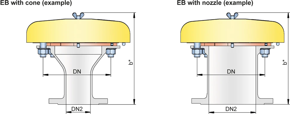
| EB-IIA and IIB with cone / nozzle** | |||||||||
| DN | 50 / 2" | 80 / 3" | 100 / 4" | 150 / 6" | |||||
| DN2 | ≤50 / 2“ | ≤80 / 3“ | ≤100 / 4 | ≤150 / 6“ | |||||
| b* | 238 / 9.37 | 263 / 10.35 | 383 / 15.08 | 313 / 12.32 | |||||
| Dimensions DN 200 - 800 / 8“ - 32“ for EB-IIA | |||||||||
| DN | 200 / 8" | 300 / 12" | 400 / 16" | 500 / 20" | 600 / 24" | 800 / 32“ | |||
| a | 405 / 15.94 | 555 / 21.85 | 705 / 27.75 | 855 / 33.66 | 1005 / 39.57 | 1210 / 47.64 | |||
| b | 177 / 6.97 | 206 / 8.11 | 235 / 9.25 | 265 / 10.43 | 294 / 11.57 | 330 / 12.99 | |||
| c | 496 / 19.53 | 650 / 25.59 | 802 / 31.57 | 987 / 38.86 | 1137 / 44.76 | 1336 / 52.60 | |||
| d | 900 / 35.43 | 1200 / 47.24 | 1500 / 59.06 | 1820 / 71.65 | 2120 / 83.46 | 2525 / 99.41 | |||
| f | 450 / 17.72 | 600 / 23.62 | 750 / 29.53 | 920 / 36.22 | 1070 / 42.13 | 1270 / 50.00 | |||
| g | 51 / 2.01 | 80 / 3.15 | 109 / 4.29 | 138 / 5.43 | 167 / 6.57 | 204 / 8.03 | |||
| EB-IIA with cone / nozzle** | |||||||||
| DN | 200 / 8" | 300 / 12" | 400 / 16" | 500 / 20" | 600 / 24" | 800 / 32" | |||
| DN2 | ≤200 / 8“ | ≤300 / 12“ | ≤400 / 16“ | ≤500 / 20“ | ≤600 / 24“ | ≤800 / 32“ | |||
| b* | 401 / 15.94 | 456 / 17.95 | 535 / 21.06 | 614 / 24.17 | 693 / 27.28 | 830 / 32.68 |
Dimensiones en mm / pulgadas
** combinations (DN/DN2) please use the table on the following page
Combination (DN/DN2) for EB with cone
Flow capacity charts for EB-DN/DN2-IIA/IIB with cone upon request
| DN | 50 / 2“ | 80 / 3“ | 100 / 4“ | 150 / 6“ | 200 / 8“ | 300 / 12“ | 400 / 16“ | 500 / 20“ | 600 / 24“ | 800 / 32“ |
| DN2 | ||||||||||
| 20 / ¾“ | IIA / IIB | IIA / IIB | IIA / IIB | IIA / IIB | ||||||
| 25 / 1“ | IIA / IIB | IIA / IIB | IIA / IIB | IIA / IIB | ||||||
| 32 / 1¼" | IIA / IIB | IIA / IIB | IIA / IIB | IIA / IIB | ||||||
| 40 / 1½" | IIA / IIB | IIA / IIB | IIA / IIB | IIA / IIB | ||||||
| 50 / 2“ | IIA / IIB | IIA / IIB | IIA / IIB | IIA / IIB | IIA | |||||
| 65 / 2½“ | IIA / IIB | IIA / IIB | IIA / IIB | |||||||
| 80 / 3“ | IIA / IIB | IIA / IIB | IIA / IIB | IIA | IIA | |||||
| 100 / 4“ | IIA / IIB | IIA / IIB | IIA | IIA | ||||||
| 125 / 5“ | IIA / IIB | IIA | ||||||||
| 150 / 6“ | IIA / IIB | IIA | IIA | IIA | ||||||
| 200 / 8“ | IIA | IIA | IIA | IIA | IIA | |||||
| 250 / 10“ | IIA | IIA | IIA | |||||||
| 300 / 12“ | IIA | IIA | IIA | |||||||
| 350 / 14“ | IIA | IIA | ||||||||
| 400 / 16“ | IIA | IIA | IIA | |||||||
| 450 / 18“ | IIA | IIA | IIA | |||||||
| 500 / 20“ | IIA | IIA | ||||||||
| 600 / 24“ | IIA | |||||||||
| 700 / 28“ | IIA |
Selección del grupo de explosión
| MESG | Expl. Gr. (IEC / CEN) | Gas Group (NEC) |
| > 0,90 mm | IIA | D |
| ≥ 0,50 mm | IIB | B |
Special approvals upon request
Selección de materiales para la vivienda
| Design | A | B |
| flange ring | Steel | Stainless Steel |
| Weather hood | Steel | Stainless Steel |
| cone / nozzle | Steel | Stainless Steel |
| Flame arrester unit | A, B, C | B, C |
Special materials upon request
Combinación de materiales para la unidad apagallamas
| Design | A | B | C |
| FLAMEFILTER® cage | Steel | Stainless Steel | Stainless Steel / Hastelloy |
| FLAMEFILTER® | Stainless Steel | Stainless Steel | Hatselloy |
| Spider ring | Steel | Stainless Steel | Stainless Steel / Hastelloy |
Special materials upon request
Tipo de bridas de conexión
| EN 1092-1 (without cone); EN 1092-1; Form B1 (with cone / nozzle) |
| ASME B16.5 (without cone); ASME B16.5 CL 150 R.F. (with cone / nozzle) |
other types upon request
Diagrama de flujo volumétrico
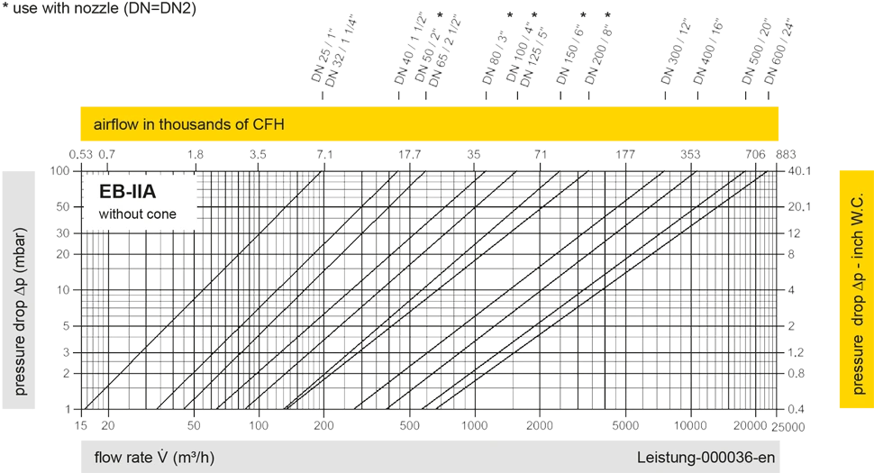
Remark: Flow capacity charts for EB-DN/DN2-IIA/IIB with cone upon request
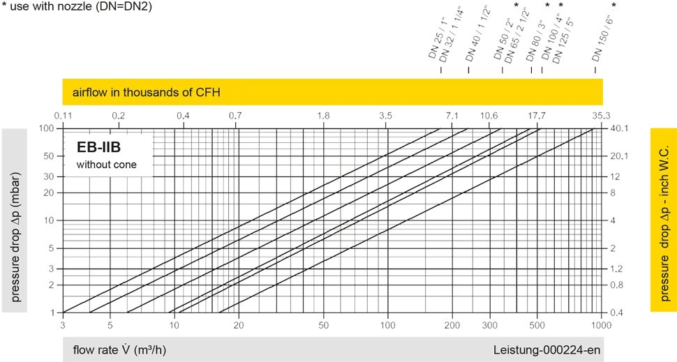
Los diagramas de flujo volumétrico han sido determinados con un banco de pruebas de caudal calibrado y certifi - cado por TÜV. El flujo volumétrico V. en [m³/h] y el CFH se refi eren a las condiciones estándar de referencia de aire según ISO 6358 (20°C, 1bar). La conversión a otras densidades y temperaturas están referidas en el Vol. 1: “Fundamentos Técnicos”.