DE/S-MK VI - IIB3
High Velocity Pressure Relief Valve deflagration- and endurance burning-proof
Features
Característica de apertura rápida
Desde el incremento mínimo de presión hasta la apertura total
Mantenimiento óptimo de la presión
Presión de tarado próxima a la presión de apertura para un mantenimiento óptimo de la presión en el sistema
Sistema de protección conforme a ATEX
Puede utilizarse como sistema de protección en zonas con atmósferas potencialmente explosivas según ATEX
Seguridad contracombustión prolongada
Protección contra deflagraciones atmosféricas y combustión prolongada
Flujo volumétrico
Flujo de caudal optimizado
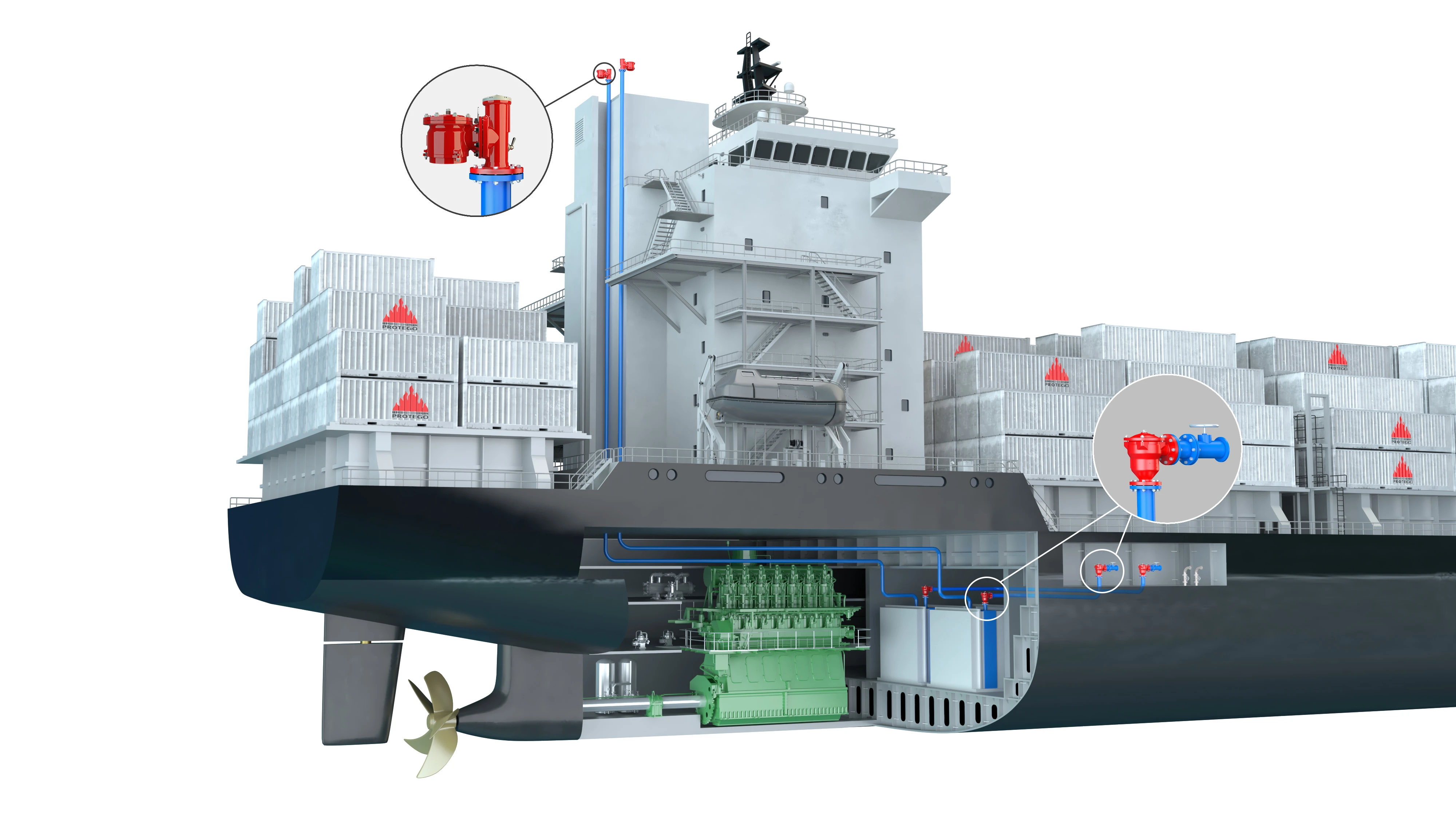
Apto para buques cisterna marítimos y fluviales
Desarrollado especialmente para buques de navegación marítima, pero también útil para buques de navegación interior y sistemas en tierra firme
Imanes permanentes
Controlado mediante una válvula de control resistente a la corrosión (válvula piloto), un imán permanente resistente a bajas temperaturas
Function and Description
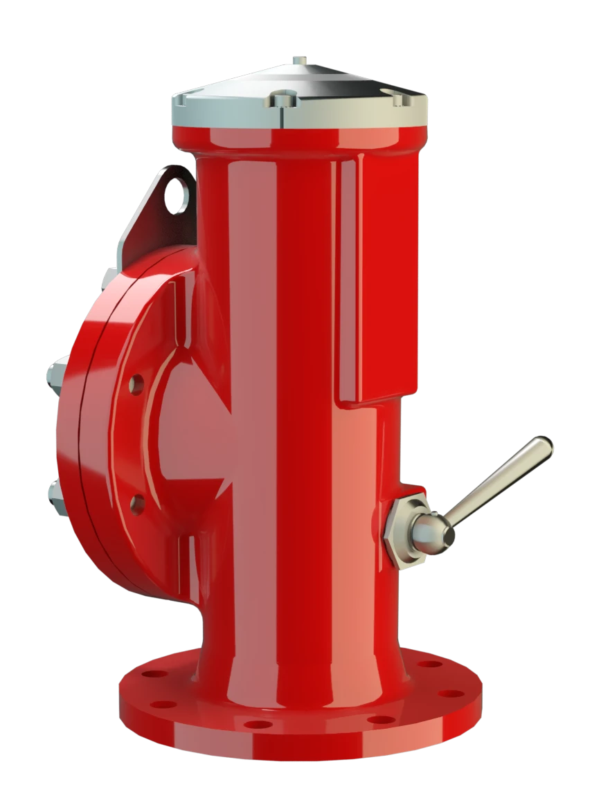
High-Speed Pressure Relief Valve
The Deflagration-Proof and Endurance-Burning-Proof PROTEGO® DE/S -MK VI type device is a state of the art high velocity vent valve working on the principle of a dynamic Flame Arrester. It is primarily used as a device for flame transmission proof venting of cargo spaces and loading systems of tankships during the loading process and on the journey. The valve offers reliable protection against excess pressure, prevents product losses almost up to the set pressure and provides protection against atmospheric deflagrations as well as endurance burning if stabilized burning occurs. The PROTEGO® DE/S-MK VI high velocity vent valve is available for substances of Explosion groups IIB3 and IIC (NEC group C MESG ≥ 0,65 mm and B MESG < 0,50 mm).
Jump Characteristic
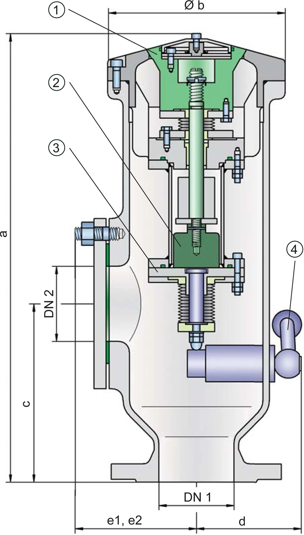
The valve cone (1) is kept in a closed position by a corrosion resistant permanent magnet (2). The set pressure is adjusted by the distance of the permanent magnet to its counterpart (3). Upon reaching the set pressure, the valve opens directly to a full lift with only a minor pressure rise (jump characteristic). The set pressure is therefore very close to the maximum allowable working pressure (MAWP) of the cargo space.

Advanced Manufacturing Technology
The tank pressure is maintained up to the set pressure with a tightness that is far superior to the conventional standard due to our state of the art manufacturing technology. This feature is ensured by valve seats made of high-quality stainless steel with an individually lapped valve cone. After the excess pressure is discharged, the valve reseats and provides a tight seal. The design of the valve cone and valve seat produces a vertical, free jet that transports the gases far away from the discharge opening. This keeps the deck free of gas. The shape of the valve cone and valve seat promotes the drainage of rainwater when closed. A function check of the valve is easily performed with a manual lift gear (4) which Returns to its initial position after actuation. A lateral flange connection, DN2, is standard for a vacuum valve (such as the PROTEGO® SV/E-S see volume 7).
Dynamic Flame Arresting Safety in Overpressure Relief Valves
If the set pressure is exceeded, explosive gas/product-vapour air mixtures are released to the atmosphere. When reaching the adjusted set pressure, the velocity at which the mixtures Exit the valve cone gap (5) (the gap between the valve seat and the valve cone) is much higher than the flame velocity. If this mixture ignites, flashback into the tank is prevented. If the mixture flow continues and stabilized burning occurs, the dynamic flame arresting feature prevents flashback ignition even in the case of endurance burning. As the system pressure decreases, the discharge velocity at the valve cone gap decreases also. The design ensures, that even in the closing pressure range, the valve cone closes in a timely manner keeping the discharge velocity far above the flame velocity and thereby preventing flashback.
Tested against oscillating flow
The PROTEGO® DE/S-MK VI high velocity pressure relief valve is also approved for oscillating flow. If a very long pipe is installed between the cargo space and valve, chattering can occur due to the resistance in the pipe or resonance phenomena. This can especially occur during partial load operation. This so called „hammering“ does not occur when a sufficient flow passes through the valve and the flow in the upstream line does not stop. The design is therefore a function of the required flow capacity. Accordingly, there are two different designs: one with a lift of 10 mm and one with 50 mm.

Many Individual Certifications
The valve can be used at an operating temperature up to +60°C / 140°F; since the valve is approved for group IIB3 (NEC Group C) vapours, it also meets the requirements of European Marine Equipment Directive 96/98/EC (MED).
EU conformity according to the currently valid ATEX directive, approved according to IMO MSC/Circular 677, 1009 by GL (the C version). Approvals according to other national/international regulations on request.
Product Data
Dimensiones
To select the nominal size (DN), please use the flow capacity chart on the following page
| DE / S with closed lateral connection DN 2 | ||||
| DN 1 | 80 / 3" | 100 / 4" | 150 / 6" | |
| a | 515 / 20.28 | 515 / 20.28 | 515 / 20.28 | |
| b | 195 / 7.68 | 195 / 7.68 | 195 / 7.68 | |
| c | 220 / 8.66 | 220 / 8.66 | 220 / 8.66 | |
| d | 120 / 4.72 | 120 / 4.72 | 120 / 4.72 | |
| e1 | 145 / 5.71 | 145 / 5.71 | 145 / 5.71 | |
| DE / S with lateral connection for vacuum relief valve DN 2 | ||||
| DN 1 | 80 / 3" | 100 / 4" | 150 / 6" | 150 / 6" |
| DN 2 | 80 / 3" | 80 / 3" | 80 / 6" | 150 / 6" |
| a | 515 / 20.28 | 515 / 20.28 | 515 / 20.28 | 515 / 20.28 |
| b | 195 / 7.68 | 195 / 7.68 | 195 / 7.68 | 195 / 7.68 |
| c | 220 / 8.66 | 220 / 8.66 | 220 / 8.66 | 220 / 8.66 |
| d | 120 / 4.72 | 120 / 4.72 | 120 / 4.72 | 120 / 4.72 |
| e2 | 100 / 3.94 | 100 / 3.94 | 100 / 3.94 | 100 / 3.94 |
Dimensiones en mm / pulgadas
Selección del grupo de explosión
| MESG | Expl. Gr. (IEC / CEN) | Gas Group (NEC) |
| ≥ 0,65 mm | IIB3 | C |
Special approvals upon request
Selección de materiales
| Design | A | B | C |
| Housing | Steel | Stainless Steel | Hastelloy |
| Valve seat | Stainless Steel | Stainless Steel | Hastelloy |
| Valve cone | Stainless Steel | Stainless Steel | Hastelloy |
| Bellow | PTFE | PTFE | PTFE |
| Gasket | PTFE | PTFE | PTFE |
Special materials upon request
Tipo de bridas de conexión
| EN 1092-1; Form B1 |
| ASME B16.5 CL 150 R.F. |
other types upon request
Diagrama de flujo volumétrico
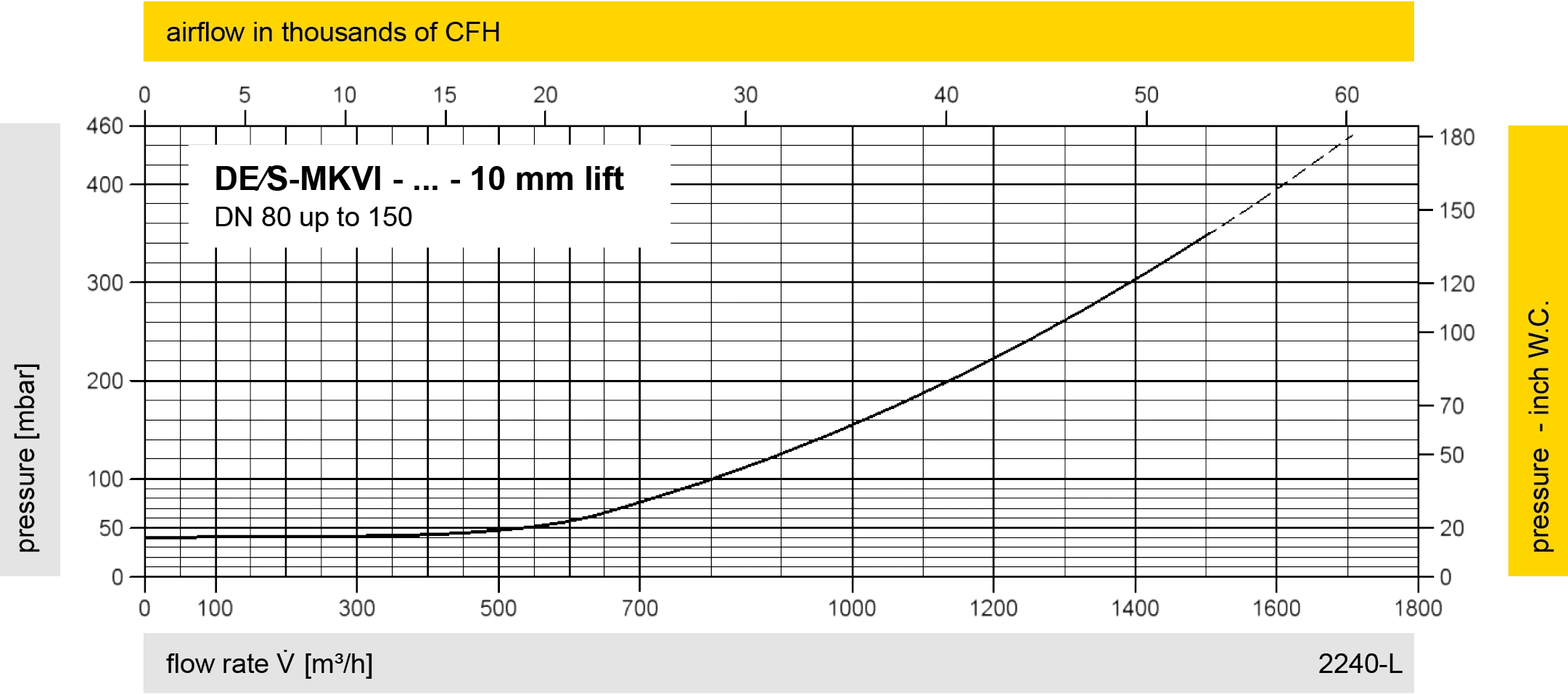
Los diagramas de flujo volumétrico han sido determinados con un banco de pruebas de caudal calibrado y certifi - cado por TÜV. El flujo volumétrico V. en [m³/h] y el CFH se refi eren a las condiciones estándar de referencia de aire según ISO 6358 (20°C, 1bar). La conversión a otras densidades y temperaturas están referidas en el Vol. 1: “Fundamentos Técnicos”.
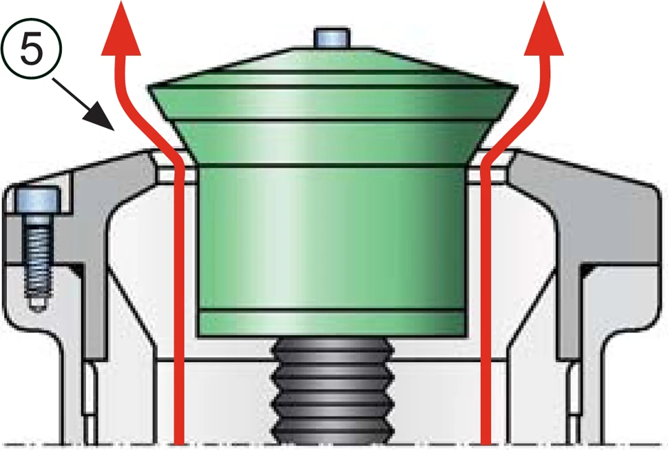
operating position of valve - open