EB-Z
Deflagration Flame Arrester, endurance burning proof, End-of-Line
Features
Seguridad frente a deflagraciones e incendios de hidrocarburos
Proporciona protección contra deflagraciones atmosféricas, combustión de corta duración y combustión prolongada de hidrocarburos puros
Protección integral contra la intemperie
La caperuza con pantalla de protección protege la unidad apagallamas PROTEGO® frente a impactos ambientales, como nidos de animales y condiciones meteorológicas adversas
Diseño modular
Permite la sustitución y limpieza de los discos de filtro FLAMEFILTER® de forma individual
Fácil mantenimiento
Sin desmontar el disco FLAMEFILTER®
Bajo coste
Bajos costes de operación y de ciclo de vida
Piezas de recambio
Piezas de recambio eficientes en costes
Function and Description
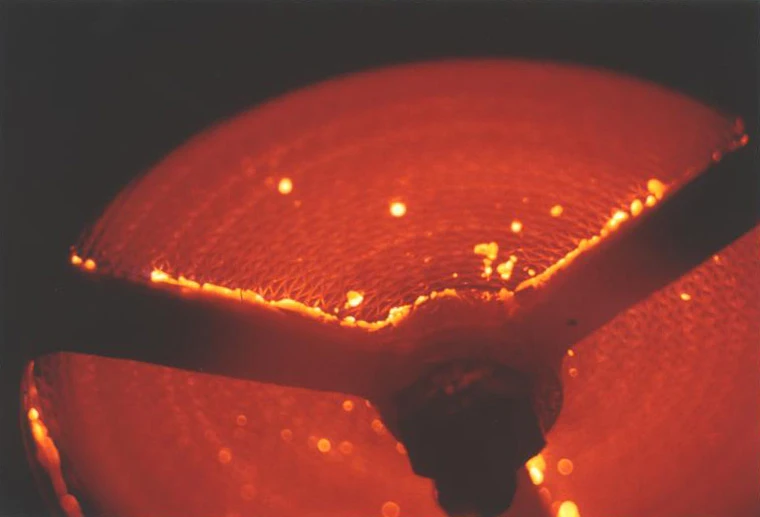
Protection Against Atmospheric Deflagration and Endurance Burning
The PROTEGO® EB-Z End-of-Line Deflagration Flame Arrester has been successfully used to protect small vessels and process engineering apparatus which are not pressurized. The device provides protection against flame transmission through atmospheric deflagration and stabilized flames which can burn for very long time on the flame arrester element surface, so called endurance burning. Main application area is on in- and outbreathing vent lines, with the goal to prevent flame transmission caused by endurance burning or atmospheric deflagration from propagating into the vessel or plant.
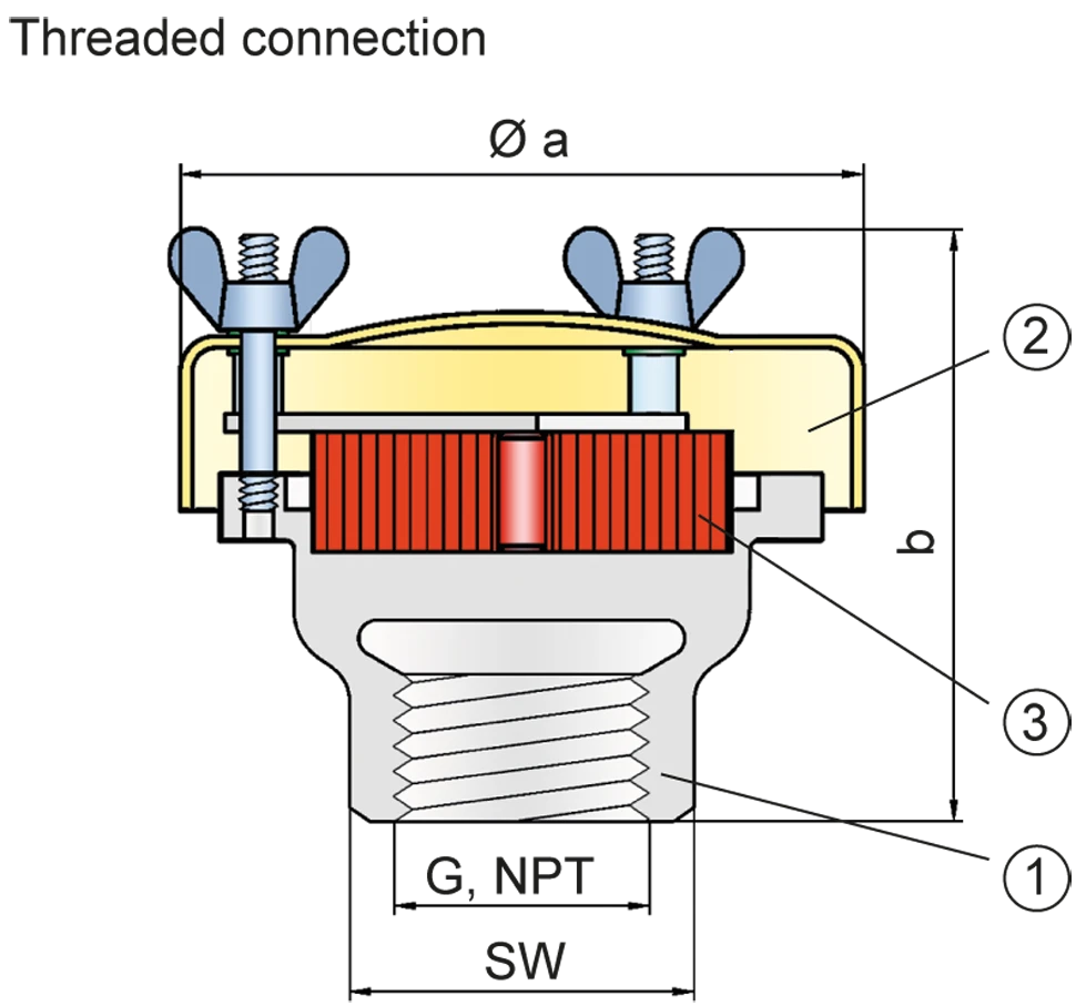
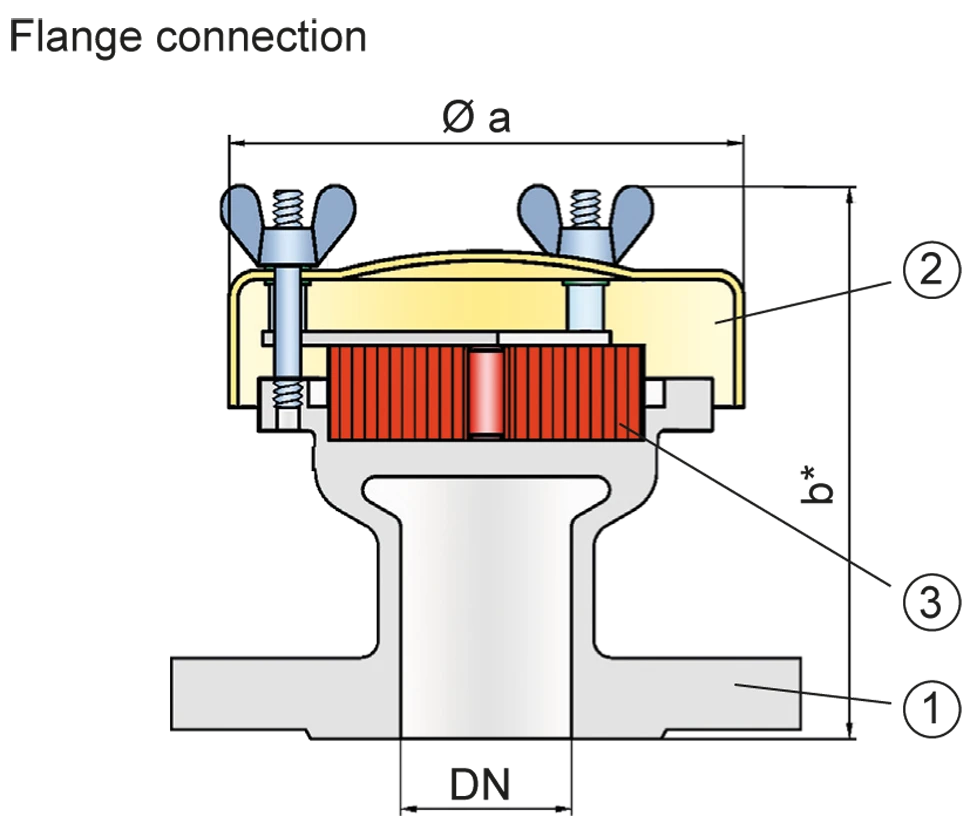
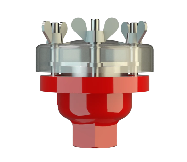
Main Component – PROTEGO® Flame Arrester Unit
The PROTEGO® EB-Z consists of a housing (1), a weather hood (2) and the FLAMEFILTER® (3). The weather hood is made out of acrylic glass, which will melt when impacted by flames and allow heat to dissipate to the environment. The PROTEGO® EB-Z Series End-of-Line Deflagration Flame Arrester is available for substances of explosion group IIA (NEC group D MESG > 0.90 mm)

Many Individual Certifications
The standard design can be used for operating temperatures up to +60°C / 140°F.
EU conformity according to the currently valid ATEX directive. Approvals according to other national/international regulations on request.
Product Data
Dimensiones
To select the nominal size (DN), please use the flow capacity chart
| DN/ G, NPT | 15 / ½“ | 20 / ¾" | 25 / 1“ | 32 / 1¼“ |
| a | 87 | 87 | 114 | 114 |
| b | 93 | 93 | 98 | 98 |
| b* | 123 | 123 | 123 | 123 |
| SW | 32 | 32 | 50 | 50 |
Dimensions in mm / inches, SW= width across flats
Selección del grupo de explosión
| MESG | Expl. Gr. (IEC / CEN) | Gas Group (NEC) |
| > 0,90 mm | IIA | D |
Special approvals upon request
Selección de materiales
| Design | B |
| Housing | Stainless Steel |
| Weather Hood | Acrylic glass |
| FLAMEFILTER® | Stainless Steel |
Special materials upon reques
Tipo de conexión
| Pipe thread DIN ISO 228-1 |
| EN 1092-1; Form B1 |
| ASME B16.5 CL 150 R.F. |
other types upon request
Diagrama de flujo volumétrico
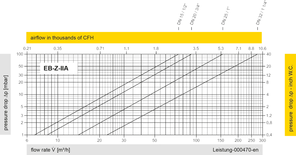
Los diagramas de flujo volumétrico han sido determinados con un banco de pruebas de caudal calibrado y certifi - cado por TÜV. El flujo volumétrico V. en [m³/h] y el CFH se refi eren a las condiciones estándar de referencia de aire según ISO 6358 (20°C, 1bar). La conversión a otras densidades y temperaturas están referidas en el Vol. 1: “Fundamentos Técnicos”.