VN-A-PCPM
Pressure/Vacuum Relief Valve Pilot-operated diaphragm valve
Features
Imanes permanentes
Controlado mediante una válvula de control resistente a la corrosión (válvula piloto), un imán permanente resistente a bajas temperaturas
Característica de apertura rápida
Desde el incremento mínimo de presión hasta la apertura total
Extrema estanqueidad
Lo que se traduce en las menores pérdidas posibles de producto y en una reducción de la contaminación ambiental
Tecnología del 10%
para un aumento mínimo de presión hasta alcanzar la apertura completa
Mantenimiento óptimo de la presión
Presión de tarado próxima a la presión de apertura para un mantenimiento óptimo de la presión en el sistema
Flujo volumétrico
Flujo de caudal optimizado
Alta durabilidad
Protección del diafragma de control de la válvula principal frente a bajas temperaturas -alta durabilidad
Se usa en zonas con riesgo de explosión
Puede utilizarse en zonas con riesgo de explosión
Baja temperatura
diseñada para su uso a bajas temperaturas
Drenaje de condensados
Drenaje de condensados automático
Kit de pruebas de campo
Pruebas de campo y suministro/instalación de kits disponibles bajo petición
Function and Description
Combined Pressure and Vacuum Relief Valve
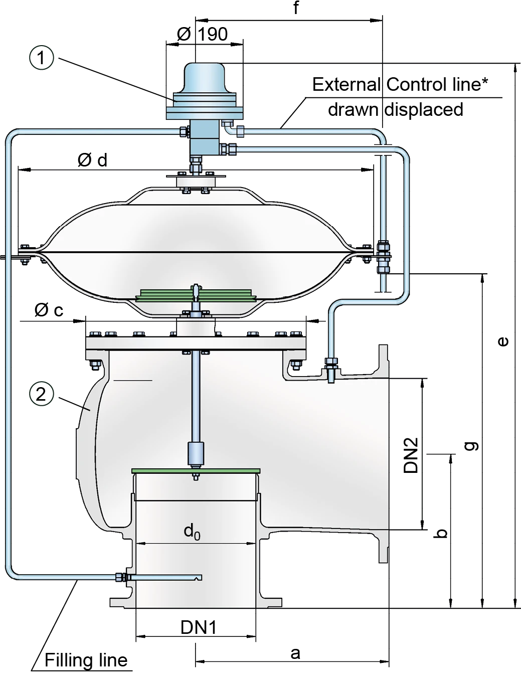
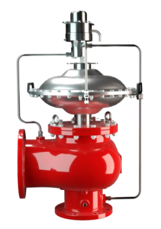
The PROTEGO® VN-A-PCPM pilot-operated diaphragm valve is a highly developed valve for pressure and vacuum relief. It is primarily used as a safety device for out-breathing in tanks, containers, and process equipment. It provides protection against unallowable overpressure and prevents the intake of air and unallowable product vapor loss up to the set pressure.The valve can also be used as an in-breathing valve where the main valve is directly controlled when it is exposed to a vacuum, i.e., it functions as a weight-loaded diaphragm valve. It is ideally suitable for both atmospheric conditions and for use in low temperatures.
Extreme Tightness
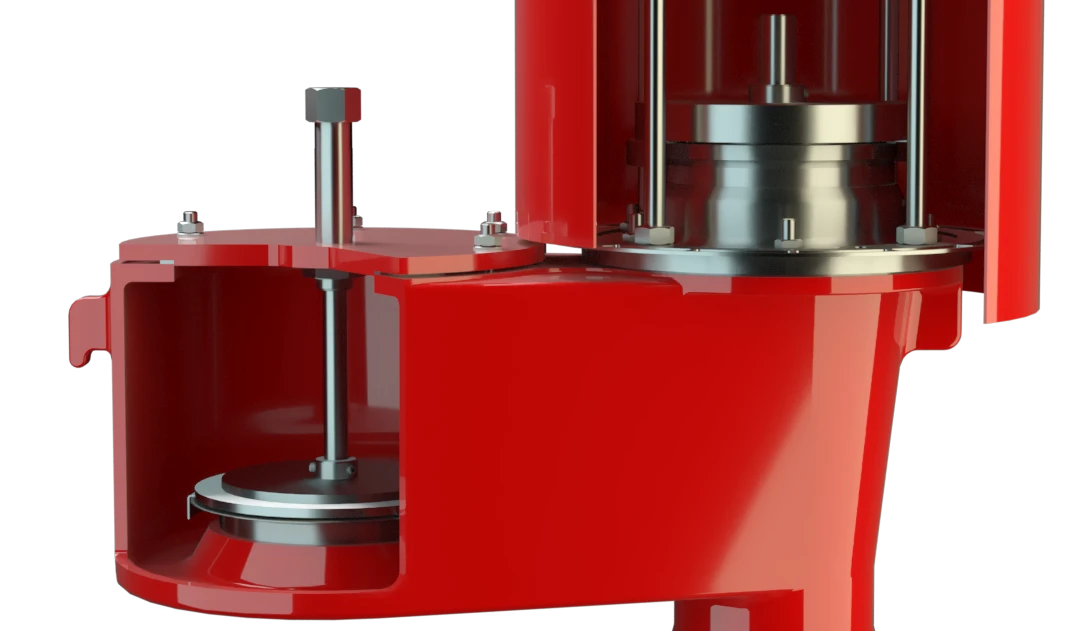
The main valve (2) is controlled by a pilot valve (1). The pilot valve is controlled by the tank pressure. The tank substance does not continuously flow through the pilot. The set pressure is adjusted on the pilot valve by a corrosion-resistant and low-temperature- resistant permanent magnet.
As the operating pressure increases, the closing force at the main valve also increases; i.e., the valve tightness increases until the set pressure is reached to prevent leakage. After the valve responds, it immediately opens completely without any significant increase in pressure (pop-open characteristic), and the nominal volumetric flow is released through a fully open valve. If this is exceeded, the pressure increase follows the volume flow (Δp/V̇ curve). From set pressure to full capacity (fully open valve), the pressure increase is 100% in case of vacuum venting/in-breathing function.
Advanced Manufacturing Technology
The tank pressure is maintained up to the set pressure with a tightness that is above the normal standards due to our state-of-the art manufacturing. This feature is ensured by valve seats made of high quality stainless steel with precisely lapped valve pallets. After the overpressure is released or the vacuum is balanced, the valve re-seats and provides a tight seal.
Product Data
Dimensiones
To select the nominal size (DN), use the flow capacity charts on the following pages
| DN1 | DN2 | a | b | c | d | e | f | g |
| 50 / 2" | 50 / 2" | 175 / 6.89 | 175 / 6.89 | 170 / 6.69 | 360 / 14.17 | 838 / 32.99 | 205 / 8.07 | 371 / 14.61 |
| 50 / 2" | 80 / 3" | 175 / 6.89 | 175 / 6.89 | 170 / 6.69 | 360 / 14.17 | 853 / 33.58 | 205 / 8.07 | 386 / 15.20 |
| 80 / 3" | 80 / 3" | 200 / 7.87 | 200 / 7.87 | 205 / 8.07 | 360 / 14.17 | 878 / 34.57 | 205 / 8.07 | 411 / 16.18 |
| 80 / 3" | 100 / 4" | 200 / 7.87 | 200 / 7.87 | 205 / 8.07 | 360 / 14.17 | 888 / 34.96 | 205 / 8.07 | 421 / 16.57 |
| 100 / 4" | 100 / 4" | 225 / 8.86 | 225 / 8.86 | 250 / 9.84 | 360 / 14.17 | 913 / 35.94 | 205 / 8.07 | 446 / 17.56 |
| 100 / 4" | 150 / 6" | 225 / 8.86 | 225 / 8.86 | 250 / 9.84 | 360 / 14.17 | 923 / 36.34 | 205 / 8.07 | 456 / 17.95 |
| 150 / 6" | 150 / 6" | 300 / 11.81 | 250 / 9.84 | 335 / 13.19 | 500 / 19.69 | 1025 / 40.35 | 275 / 10.83 | 531 / 20.91 |
| 150 / 6" | 200 / 8" | 300 / 11.81 | 250 / 9.84 | 335 / 13.19 | 500 / 19.69 | 1045 / 41.14 | 275 / 10.83 | 551 / 21.69 |
| 200 / 8" | 200 / 8" | 375 / 14.77 | 300 / 11.81 | 410 / 16.14 | 630 / 24.80 | 1237 / 48.70 | 340 / 13.39 | 638 / 25.12 |
| 200 / 8" | 250 / 10" | 375 / 14.77 | 300 / 11.81 | 410 / 16.14 | 630 / 24.80 | 1188 / 46.77 | 340 / 13.39 | 668 / 26.30 |
| 250 / 10" | 250 / 10" | 425 / 16.73 | 350 / 13.78 | 500 / 19.69 | 790 / 31.10 | 1278 / 50.31 | 420 / 16.54 | 738 / 29.05 |
| 250 / 10" | 300 / 12" | 425 / 16.73 | 350 / 13.78 | 500 / 19.69 | 790 / 31.10 | 1298 / 51.10 | 420 / 16.54 | 758 / 29.84 |
| 300 / 12" | 300 / 12" | 500 / 19.69 | 400 / 15.75 | 570 / 22.44 | 920 / 36.22 | 1389 / 54.58 | 485 / 19.09 | 831 / 32.72 |
| 300 / 12" | 350 / 14" | 500 / 19.69 | 400 / 15.75 | 570 / 22.44 | 920 / 36.22 | 1409 / 55.47 | 485 / 19.09 | 851 / 33.50 |
| 300 / 12" | 400 / 16" | 500 / 19.69 | 400 / 15.75 | 570 / 22.44 | 920 / 36.22 | 1429 / 56.26 | 485 / 19.09 | 871 / 34.29 |
Dimensiones en mm / pulgadas
Selección de materiales para la vivienda
| Design | A | B | C |
| Housing | Aluminium | Stainless Steel | LTCS* (Low Temperature Carbon Steel) |
| Valve seat | Stainless Steel | Stainless Steel | Stainless Steel |
| Sealing - housing | PTFE | PTFE | PTFE |
| Sealing – valve disc | metal - to - metal | metal - to - metal | metal - to - metal |
| Housing diaphragm | Stainless Steel | Stainless Steel | Stainless Steel |
| Pilot lines | Stainless Steel | Stainless Steel | Stainless Steel |
| Pilot housing | Aluminium | Aluminium/ Stainless Steel | Aluminium/ Stainless Steel |
| Pilot diaphragm | FEP | FEP | FEP |
* Special materials upon request
Tipo de bridas de conexión
| EN 1092-1; Form B1 |
| ASME B16.5 CL 150 R.F. |
Other types upon request
Coefficient of Discharge
| DN1 | 50 / 2" | 50 / 2" | 80 / 3" | 80 / 3" | 100 / 4" | 100 / 4" | 150 / 6" | 150 / 6" | 200 / 8" | 200 / 8" | 250 / 10" | 250 / 10" | 300 / 12" | 300 / 12" | 300 / 12" |
| DN2 | 50 / 2" | 80 / 3" | 80 / 3" | 100 / 4" | 100 / 4" | 150 / 6" | 150 / 6" | 200 / 8" | 200 / 8" | 250 / 10" | 250 / 10" | 300 / 12" | 300 / 12" | 350 / 14" | 400 / 16" |
| d0 | 54 / 2.13 | 54 / 2.13 | 83 / 3.27 | 83 / 3.27 | 108 / 4.25 | 108 / 4.25 | 160 / 6.30 | 160 / 6.30 | 208 / 8.19 | 208 / 8.19 | 262 / 10.31 | 262 / 10.31 | 310 / 12.20 | 310 / 12.20 | 310 / 12.20 |
| K | 0.57 | 0.75 | 0.63 | 0.71 | 0.60 | 0.75 | 0.64 | 0.78 | 0.63 | 0.76 | 0.62 | 0.73 | 0.63 | 0.68 | 0.74 |
DN1 = size inlet
DN2 = size outlet
d0 = orifice diameter(mm / inches)
K = coefficient of discharge
Diagrama de flujo volumétrico
Los diagramas de flujo volumétrico han sido determinados con un banco de pruebas de caudal calibrado y certifi - cado por TÜV. El flujo volumétrico V. en [m³/h] y el CFH se refi eren a las condiciones estándar de referencia de aire según ISO 6358 (20°C, 1bar). La conversión a otras densidades y temperaturas están referidas en el Vol. 1: “Fundamentos Técnicos”.